Depending on the selected rotation output axis A or Y, the generated gcode is different. For the A axis, the speed of the 2 axes (X and A) is permanently adapted according to the angular position until reaching a value close to 0, while for the Y axis the speed is constant for the 2 axes and only the variation of the Y coordinates is adapted according to the angular position of rotation. In the case of use with the Y axis in rotation it works perfectly well. In the case of use with the A axis used in rotation, the cycle time is increased tenfold and the laser power is not regulated with the speed. My question is: Why is the gcode generation algorithm different for the A and Y axes? And is it possible to generate the same type of code for the A axis as for the Y axis? This will save me from having to connect my A axis motor to the Y motor output every time I do rotary engraving.
Thanks in advance for your feedback
By definition Y axis is linear and A axis is angular(rotary).
Post your device configuration .lbdev and maybe we could set a Custom device.
Thanks for the feedback. My A axis is indeed configured to be rotary on my machine, but the results are much better using the Y axis in rotary with the output algorithm for that axis in Lightburn. My question was is it possible to get the same type of algorithm intended for the Y axis for the A axis, is there a way, a parameter, an adjustment to make to achieve this?
Maybe comparing GCode Y vs A…
You can also fine tune your laser power e.g. more 5% or 10% power or maybe your A acceleration.
I found an interesting solution to get around the problem. In the gcode file initially generated for the Y axis, I replace the letter Y with the letter A. I can thus leave my motor connected to the A axis and everything works correctly.
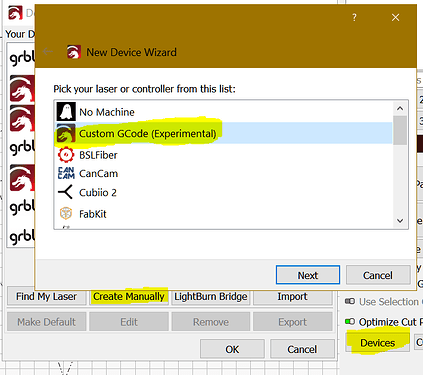
If that works, also regarding the size of the shapes maybe you can create a Rotary_CustomGCode that auto-outputs the changes you need.
Thanks for the advice, but how do you make a Rotary_CustomGCode ?
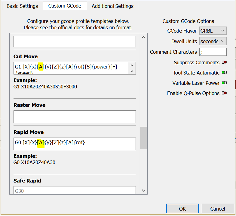
What is the syntax to replace Y axis with A axis in custom Gcode?
Did you check the correct lasered shapes size?
Maybe your A is linear…?? I believe if you have an object with 100mm circumference it´s the same if you move it 100mm on Y or 1 rotation (or 360º) on A.
.
Change the highlighted to A and keep your rotary axis at Y.
Yes, the proportions and scales are respected in rotation mode. Thank you for your advice, it is indeed a solution that works with your example. The problem is to re-enter the Y axis when I switch back to linear mode in the custom gcode, which produces as much work as replacing the letter Y in the gcode file with an editor.
Thank you for your valuable advice.
No need to do that.
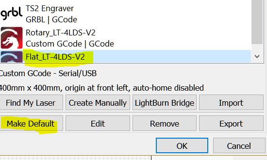
In Device settings select your Flat device and click Make Default then OK.
Keep your Rotary_CustomGCode edited, when you need/want to do rotary.
If you enable rotary in your Rotary_CustomGCode and leave without disabling it, Lightburn keeps the switch position per device so that you need only to alternate between flat and rotary.
You are absolutely right, making 2 Gcod customs one for flat work and the other for rotary work is very clever. Everything is now optimized and works as expected.
Thank you very much for your valuable advice!!!
This topic was automatically closed 30 days after the last reply. New replies are no longer allowed.


