I’m having some issues cutting pieces. When I use line for cutting a material, sometimes the start point and the end point is not the same, so the cut is not good. The difference is of a mm o so, I also tried to use 2 different operations, but the result is quite strange.
I’m using a Black/Red machine with a Ruida RDC6442S-B.
Attached are some pictures to explain this error.
This is the result, using a close line: Cut1|690x388
I Also tried using lines + close lines to make the rounded corners:
And this is how I did it finally… having a similar problem, because the last cutting line was not in the same place:
That looks like your machine has a very large mechanical backlash - something loose in the motion system, like a belt, pinion gear, set screw, coupling, bearing, etc. If anything in the motion hardware of the machine is loose, things will not line up properly.
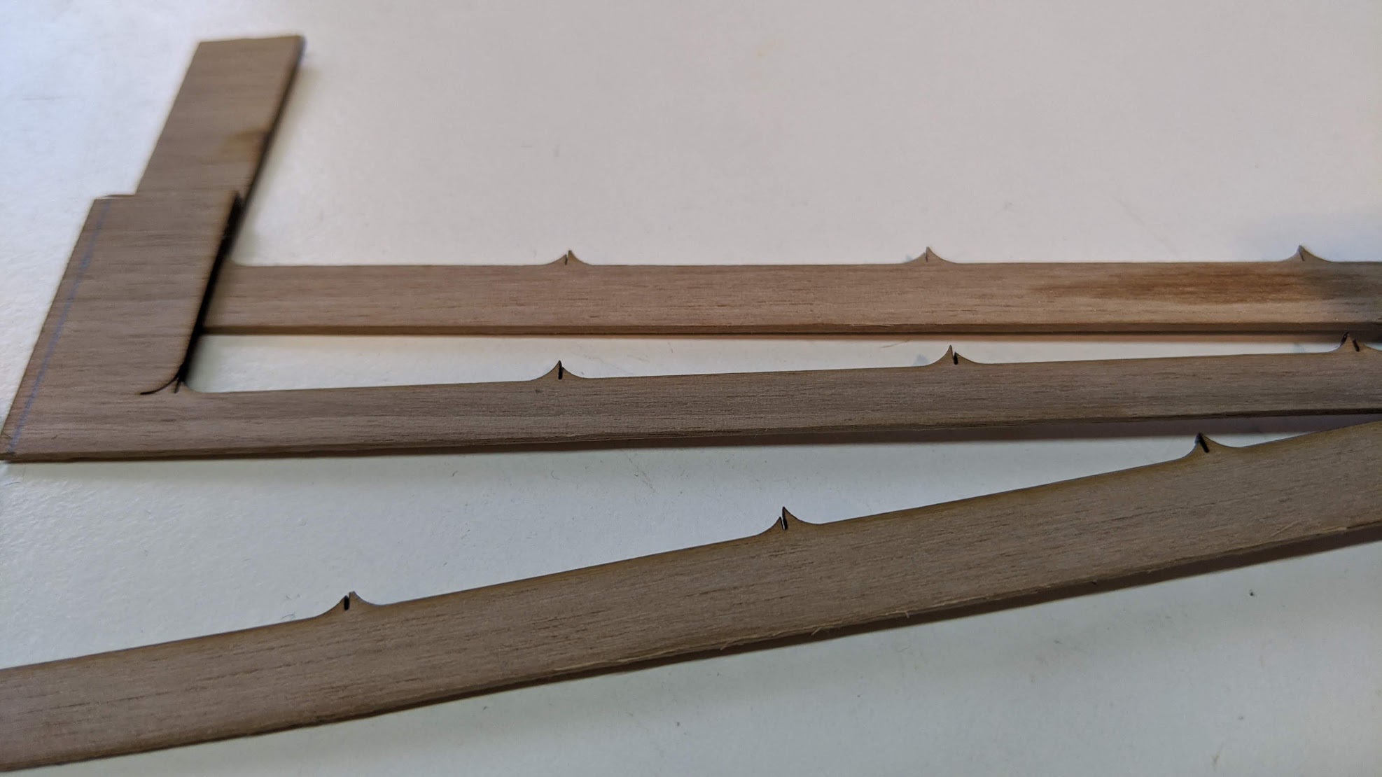
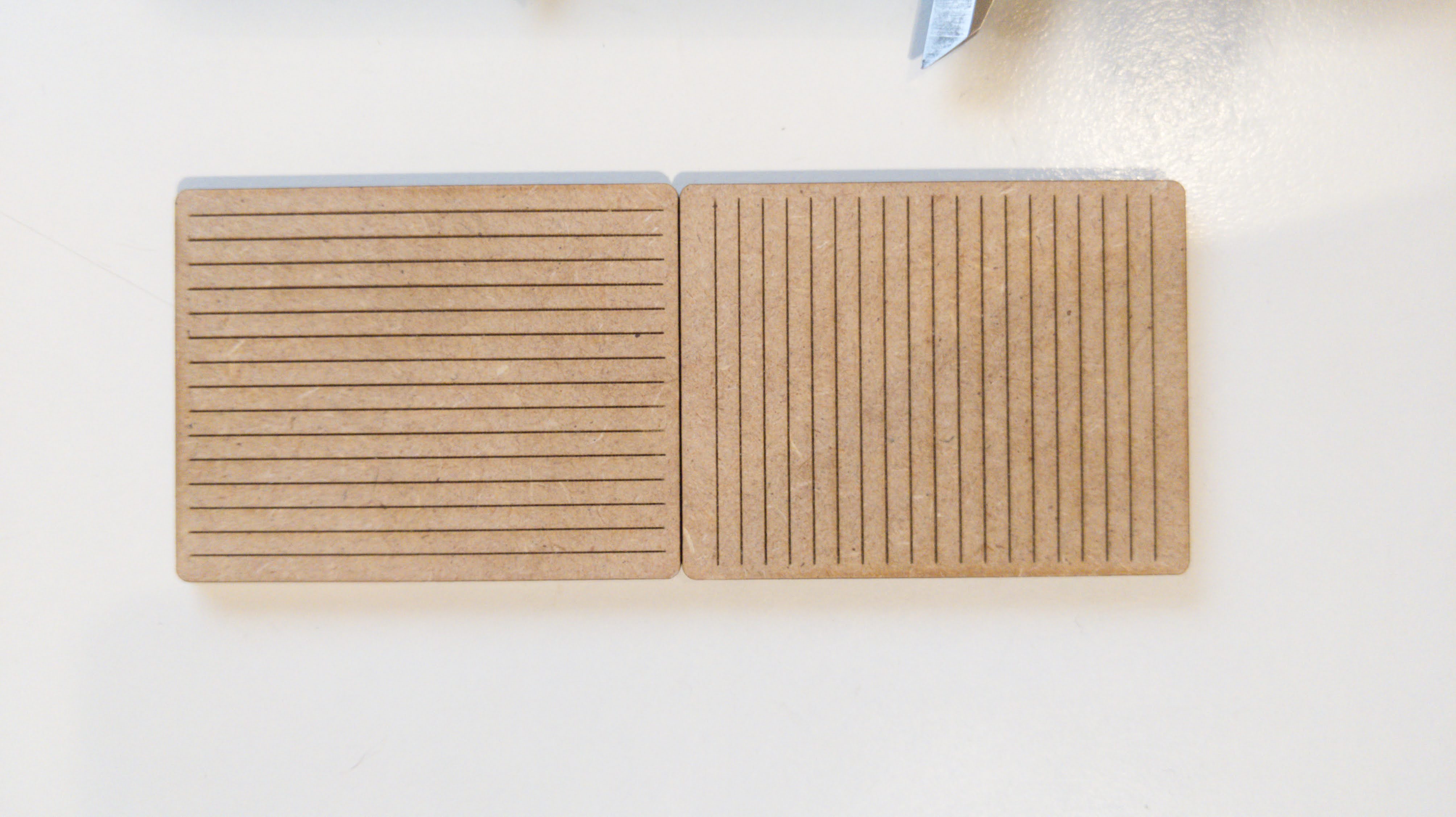
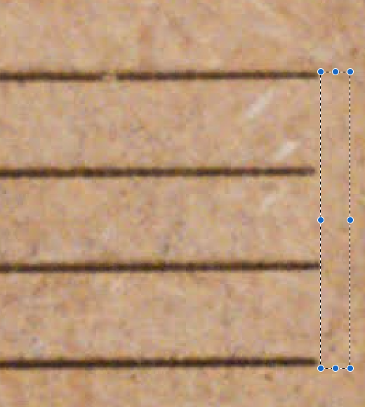
The way to test for this is to draw a series of lines just x axis, then just y axis, and ensure your settings make it go from the nearest point so they alternate in direction when being burned.
That will magnify the effect the most, as backlash will be taken up in both directions, thus the ends will be twice the actual backlash amount. Doing vertical and horizontal will show whether it’s in both axes or just one.
I was looking for some mechanical issues, at the beginning I realise that the belts were not tight enough, good but not enough. But the main thing was that the Y axis, was not aligned so I had to put both parallel. The linear rails were not perpendicular to the X axis, I also had to unscrew a bit one of the rails and then screw again in a better position, due to this, I had some mechanical noise when the X rail was near the end of Y axis and some tremble at the carriage beacuse of the misalignment.
The thing is that after all, the problem continues… I made the X Y test Bonjour said, and this is the result:
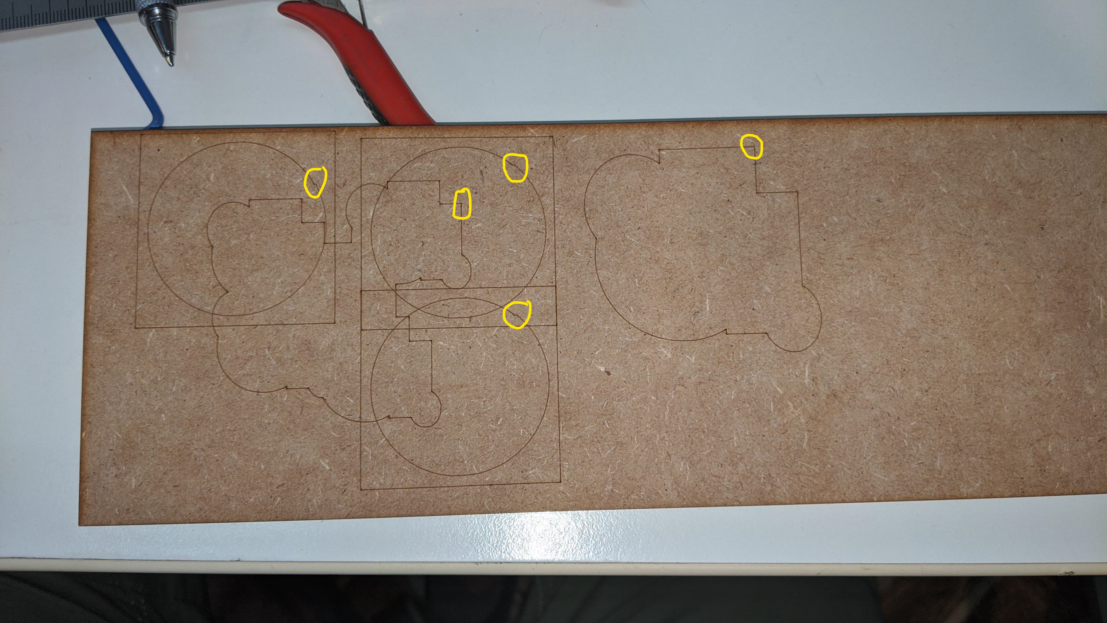
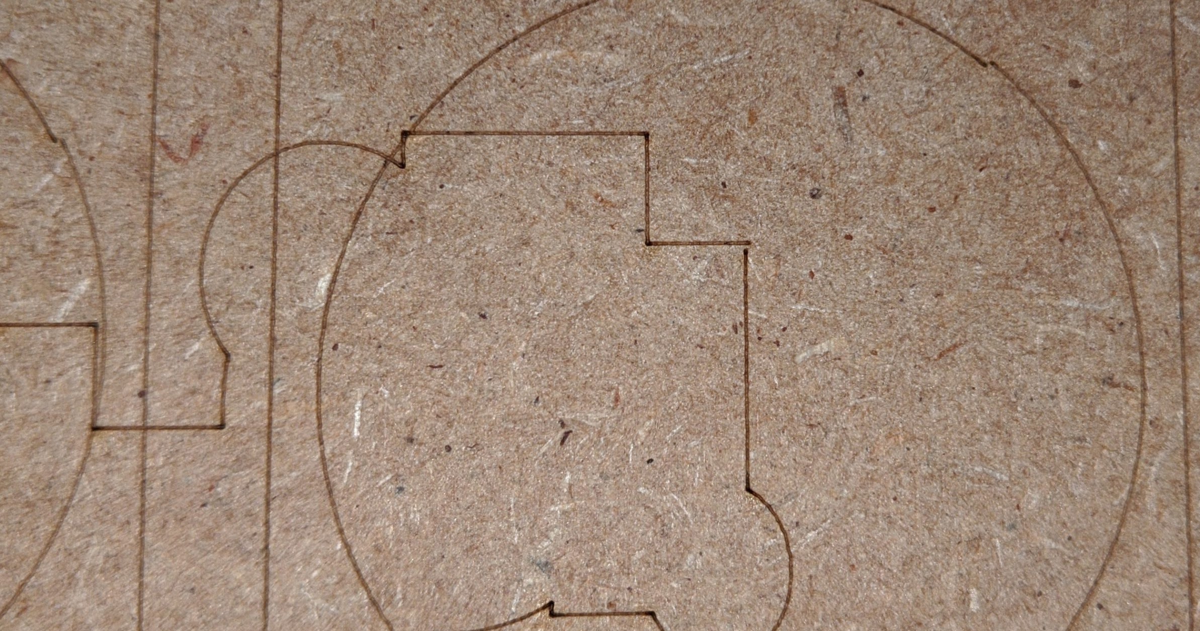
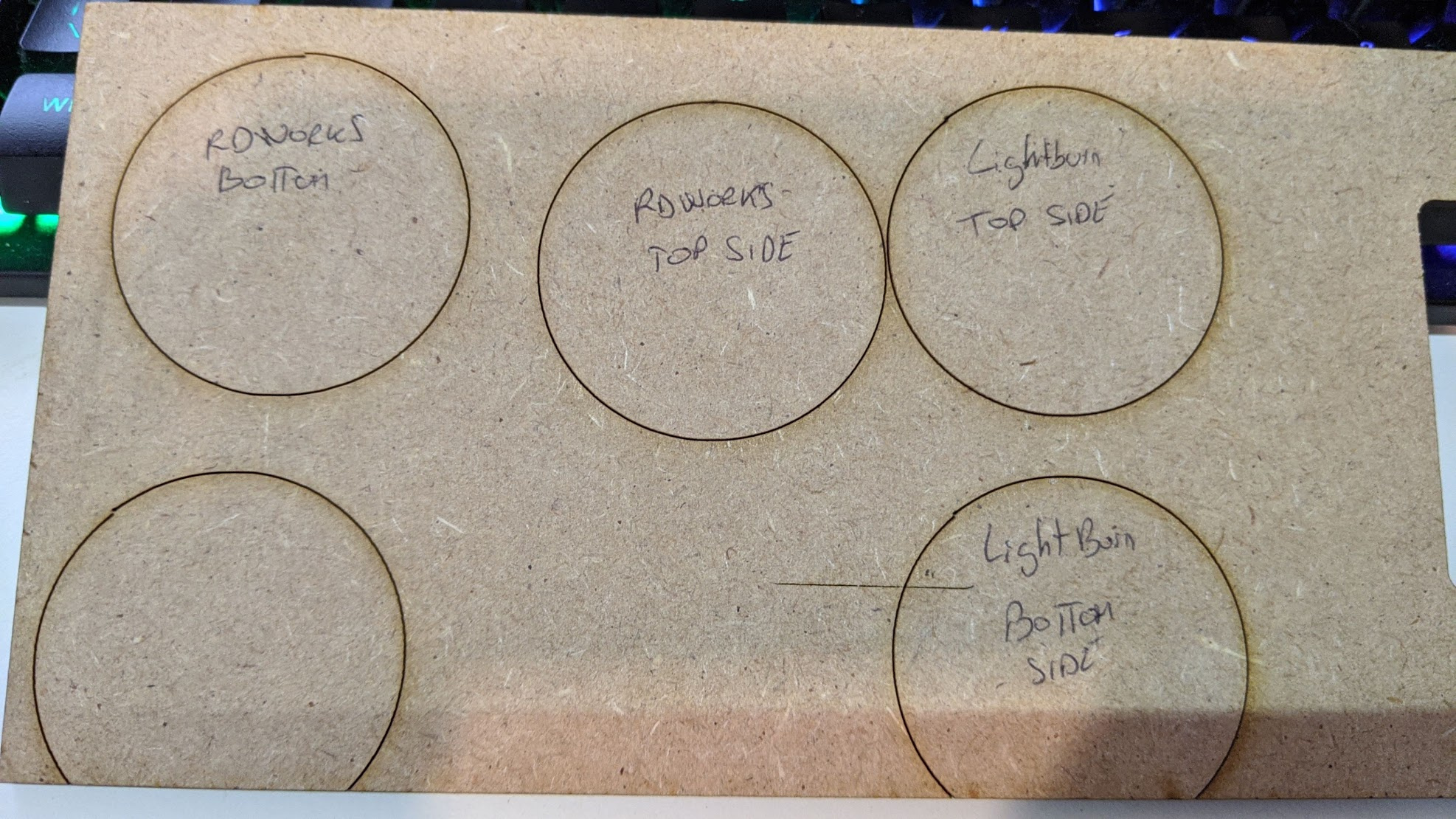
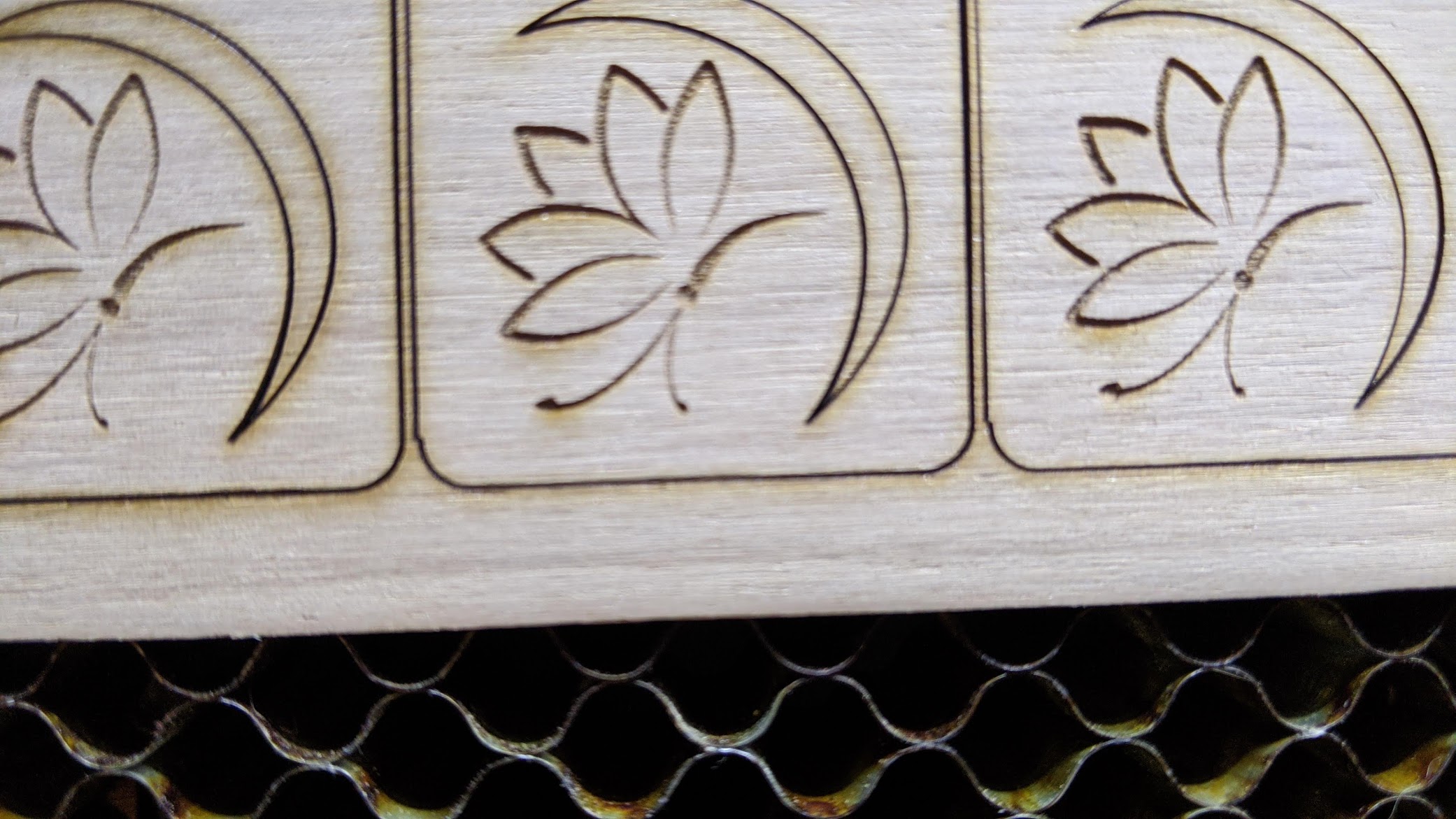
I also made some test more and the problem with the circle was the same, but what I can’t understand is why engraving a intrincate figure, the result is better than with a single circle. In fact I tested to make a figure and after that a copy of the same figure with a different size and the misalignment at the final point is the same. Here is a picture of all the last tests.
The next release of LightBurn improves the behavior of the ‘Hide Backlash’ option in the optimization settings, but you should fix as much as you can mechanically first.

