Dimensional accuracy issues Creality Falcon 2 22W


I used Creality Falcon 2 22W for almost a year without much problems.

Until today, when I tried to cut a 2.4mm acrylic plate of 190 x 122mm dimension. The end product was 191 x 122.5mm.

I browsed the internet and did the following things:

  1. tightened belts
  2. tightened the nut behind the laser module
  3. Reset the Machine
  4. updated the firmware to the latest version.

Nothing helped, so lastly I tried the calibrate axis option on Lightburn, here is where it gets absurd:

Without calibration a rectangle cutout of 45 (X axis) x 30(Yaxis) measured 44.75 and 29.65mm.

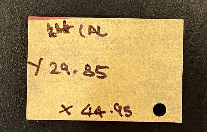
After first calibration, the cut measured 44.95(X)and 29. 85(Y)mm

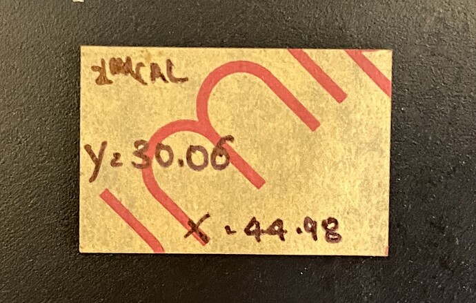
After second calibration, the cutout measured 44.98(X) and 30.05(Y)mm

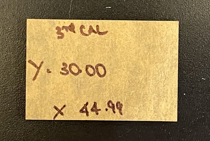
After the third calibration the cutout measured 44.99 (X)and 30.00(Y)mm

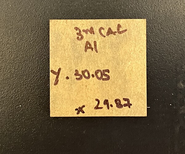
I thought I solved the issue and proceed to cut a different dimension of 30(X axis) and 30(Y axis) mm, the end result was 29.87 ( X) and 30.05 ( Y axis)

Confused, I once again tried the calibration cutout of 45(X axis) and 30( Y axis) and the results were fine. They were 44.97(X) and 30.05(Y)mm

Can somebody help me understand whats going on?
You are trying to calibrate when you still have a machine backlash problem. You did not mention checking the set screws on the pulleys and couplings. If that ain’t right, nobody is right.

1 Like

Could you please elaborate how to properly tighten the screws and belts to solve the backlash?

Is there a way to confirm out if the tightening done is sufficient?

This guide should help you. Although it says Sculpfun, the information applies to many machines.

@MikeyH thank you so much for the article. This article along with Creality maintenance article shared by @Woodcraft was valuable.

I did a couple of things:

  1. Rechecked the belt tightness and found that when compared to the maintenance video my belts were too tight.
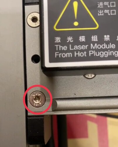
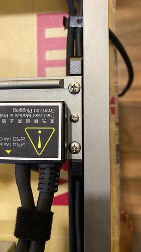
  2. There was a bit of movement in the X axis frame, the M4 screws used to mount the X axis to Y axis are countersink type and over time the hole on the metallic frame has probably got slightly enlarged and it was not holding it firmly even though the screw was fully tight. After replacing it with a Pan Head type screw there was no more play.
  3. After all this, the cutout reading stabilised at (-0.25mm). I then used Kerf Offset option in layer cut setting to adjust rather than calibrate axis.

I have tried different cutouts dimensions ranging from 20 mm to 190 mm and the results are accurate and consistent

Thank you

1 Like

That is good news! Thanks goes to the Lightburn community, not just me.

Be sure to mark this as solved so others can find it.

1 Like

how do I mark a solution on this platform?

Yeah, I was wondering the same thing. Ringing @JohnJohn for help…

Exactly!

To confirm which adjustment is needed it’s best to generate a minimum of two tests.

Testing with two squares, using the factory axis calibration, and no kerf offset adjustment, it’s fairly safe to assume that most variation from the design would be either the axis calibration or the kerf.

First check the axis calibration by engraving two squares (different sizes) using the thinnest visible line you can engrave on scrap material. A thin engraved line offers the most precision.

When you compare the sizes of the two squares you engrave to the design, If the error increases as the square gets larger, generally the axis calibration should be adjusted.

If the error is the same when comparing a larger square and a smaller square to the design, the Kerf offset should be adjusted.

Testing with the lowest speed and lowest power may reduce other potential errors caused by acceleration.

This is an excellent find. Did the end of the countersunk screw hit the bottom of a closed or “Blind” threaded hole or did the leading edge of the countersink reach the top of the threaded hole?

This is a good solution. I feel that would have been a tough problem to find.

With a pan head bolt, you may be relying on the sharp edge of the bottom of the original countersunk hole to locate the two components. With the ‘location’ of the components being loose, they become slightly adjustable. You can install the screws with a thread-locking compound (like purple Loc-Tite) and line up the mechanical components with a small Carpenter’s Square when you assemble that part of the engraver.

The ‘Mark as solved’ functionality isn’t enabled in the Community section. This is =certainly a noteworthy hardware solution.

Most of the Creality hardware historically, used to run on Marlin. Previous posts would likely have been seen as Marlin-related and moved to the Marlin section.

The Falcon is a GRBL Device.
I can move it into the GRBL section for now to mark it solved.

1 Like

This was how the machine originally was, with two countersink screw. You can observe that hole is slightly large than the head of the screw, which resulted in play as shown in the below video.

To solve this, I used 2x M4 6mm pan head screws and 1x M3x 6mm Pan head screw as shown below. There absolutely no play even when I tried my best.

Like @JohnJohn mentioned I tried 2 sizes without any kerf offset to check if the reading were same. All of them had a tolerance of .25mm -.30mm.

Thats when I used kerf offset to bring to exact dimensions. After which I tired cutting 3mm acrylic plate of dimensions 20mm x 20mm and 190mm x 120mm, both came out perfect.

Frankly I had given up on the belt as there isn’t a standard value I can fall back on to check the tightness.The industry grade instruments cost way too much end of the day it comes down to using a microphone and using frequency vakues to calculate the stiffness but even then without Creality’s input on exact stiffness value the whole process be it microphone or industry grade equipment, falls back to the domain of trial and error.

But @MikeyH and @Woodcraft inputs helped get through this entire ordeal.

I remember Prusa MK3S having a method of approximating belt tightness with a number steps being counted. I hope other companies try something similar, makes the maintanence accurate and repeatable.

I do have to accept probably a little more tweaking on the belts could have reduced that kerf offset values by a bit.

But for now I am planning to wait until there is need to intervene and recheck again.

Thank you @JohnJohn for your inputs. This forum has helped a great deal :smile:

2 Likes

This topic was automatically closed 30 days after the last reply. New replies are no longer allowed.