I’m hoping to get some advice on which laser module I should purchase based on kerf thickness. We are only going to cut wood veneer with this, so power isn’t the biggest concern, but kerf thickness is as we are creating marquetry. Is anyone aware of certain modules that are better suited for this sort of detailed cutting? Our current laser has a kerf of .15mm which works with our workflow, but I would like to tighten that up.
Kerf is always a function of power (multiplies of ~5,5W optical on the typical budget laser modules) and material thickness.
So without knowing those two variables, it’s next to impossible to predict what the kerf/width of the cut is going to be.
So, we need more information in order to even guess what laser suit Your needs the best.
I’m not a native speaker (no surprise there I assume ) but from the op I understood that they want to use the leftovers as well.
As is usually the case in marquetry.
No worries, I’m picking up what you are saying. Using leftovers would be great, but, even at .08mm that would be challenging with our process. I have used a drag knife for that reason but that introduces all sorts of challenges with material inconsistencies. I now only use it to cut base material for our skis as that is a homogeneous material.
Tuning isn’t a big concern, I just don’t want to empty my wallet at Thorlabs.
No matter what the kerf, it has to be dealt with. Dpssl lasers don’t have round beams, they are rectangular, so the kerf will change depending on the engrave/cut direction.
Can you handle the difference in material between 0.15mm and 0.10mm? Are you going to save anything material wise with an extra 0.05mm?
It’s more about compounding errors across multiple intersections. If there are say 5 cuts then the last one will be .2mm out of position. That might be visible, but I didn’t think about the rectangular nature of the diode, that will be a new challenge. We use Epilog Helix 24 currently, it’s a RF C02 tube. Does Lightbeam’s kerf compensation work around this rectangular projection.
In that case You’ll probably get by with 5.5W head.
But…
The tradeoff (isn’t there always ) then is the cutting speed.
The problem lies in the way higher power budget lasers are made, by combining two or more beams into one, and focusing that beam.
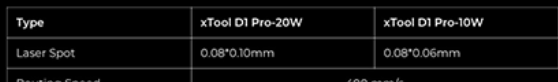
The optcis involved mean that the focus size increases as more beams are merged into one, and at least with the XTool 20W, the focus isn’t round but an oval in shape.
Ok, then it’s just the matter of using the kerf function in LB.
That’ll take care of that problem, and in fact You can probably use the existing laser as well, as then the beam width doesn’t matter that much.
The reason I thought You’re going to use the leftovers as well, is that some of the people I have known have at least tried to be able to make two marquetry pieces from the two (or more) veneers, one “normal” and one “negative”.
And also because if the leftovers aren’t going to be used, the beam width/kerf doesn’t matter because it can -and have to- be compensated.
At least the beam on the XTool D1 20W I have is rather “round” than rectangular, as is the XTool 2W IR as well.
I should mention for the Epilog, since it doesn’t do kerf compensation, we have a script to do all of that manipulation inside of Illustrator. Over the years, I’ve gotten it down to a simple button click to calculate all offsets and send them to the laser. I might be able to alter it to compensate for non-uniform beams. This is mostly trying to get around some of the challenges we have had with kerf and my own experiences with cheap modules that are poorly collimated. I do my best to steer people away from thin designs which makes it possible to compound errors in a small space, but I only plan on building this once, and if I can head off any headaches, then it’s worth it in the long run.
Ok, that’s strange.
Kerf or tool compensation is a vital part of any material removing method, be that by hand or by machine.
But since:
Your Epilog laser controller obviously does allow the use of a third party files (not all lasers do AFAIK) and just runs the code created with that software.
I do have to admit that I have only used this XTool of mine, and had a brief encounter with large industrial metal cutting lasers some ~25 years ago while in Poly, but I have always used a CAD program for the designing part and imported those files into the controlling/CAM software.
And that software is obviously LB with XTool .
With those industrial lasers it was the manufacturers CAM software, and the compensations, lead-ins and -outs etc. were handled with that software.
There’s obviously -since You’ve done just that- a workaround if the machine or its CAM software for some reason doesn’t handle kerf compensation, and that is obviously by putting the compensation into the design.
But unless there’s a “work” file, and a separate (automatically updated?) file with the compensations, at some point those two will mix and at best the cleaning up will take a lot of time, at worst the design has to be scrapped and started again from scratch.
There’s also a very good reason why that “including the compensations into the design” approach isn’t popular in CAD/CAM circles regardless of whether it’s a professional or hobby work, and regardless of the method of material removal, and that is the fact that the design/file is tied to one specific machine that is adjusted and tooled the same exact way.
If anything changes -and it inevitably does- the result is incorrect.
good luck with that.
Sometimes the claims made by the marketing department and the reality doesn’t quite meet .
I can obviously only claim what kind of beam shape the heads my laser came with have, but the agreements (usually incorrectly dubbed as laws) of optics/physics don’t exactly make it easy to produce a rectangular beam of light.
One would even be inclined to claim that’s impossible (at least in this price range), not to mention impractical since the energy density would be reduced ~20%.
That same ~20% is behind the fact why SMD leds and virtually every other consumer grade semiconductor product is rectangular in shape.
While making other things more difficult, that shape reduces the silicone base material waste by ~20% when compared with circular shape.
I’ve been doing marquetry for a while using veneers and my OLM3 (10W)
Generally the cut parameters need to be different for each type of veneer as there is burning which you want to minimize.
I suggest just plain old trial and error.
Generally I’ll use a “0.00” kerf offset for the outer shape then use the offset (0.04 outward) in my case to get a good fit for the interior bits. If you go for too tight you might have to hand-prepare each part with light sanding. I you sand away the burned edges anyway, you’ll need to compensate.
(10" x 8" panel recently created with quilted maple, fumed etimone, yellow heart, and aspen.
Maybe true, but when the source is rectangular, there has to be a similar output or some kind of tradeoff…?
My camera has no problems with rectangular parts in the image… maybe I’m too broad with this claim, but even my fiber uses F (flat field lenses) type to focus the beam onto a flat surface.
I’d like to see the dot produced by your laser… Most of what I see is from co2 and are round… do you have a photo of your spot?
Diode emitters are not point sources. At the junction inside the device they are rectangular. Just the physics needed to create them.
If your focused spot is a defined rectangle, then your optics are good (no distortion).
Mulit-diode lasers have the beam combiners which if the source diodes are rotated slightly or have an shifted position, can produce non-rectangular “spots”. Both sources being in phase is what matters most here.
I teach a ski/snowboard building class using marquetry for the top sheets. This is a board I made with a simple top sheet as an experimental design. Not quite as finely made as brewster’s design but it is a very fun board.
The diode spot shape is something I can check pretty easily. I’ll cross that bridge if I need to.
I have no personal experience, but you may want to look into an OPT diode head. They advertise some impressive beam spots with adequate power for your application.
If the pic is a true representation of the actual spot, that’s extremely impressive.
Looks more like a thermal camera shot of the actual led though, not to mention it doesn’t quite look like the 10um4um (0.5W) nor the 50um4um (6W) spot in the specs .
But, impressive in any case, and the price/W represents that well as can be imagined.
Tighten? Not understanding your meaning here. If it is the size of the beam produced…,
When investigating kerf size, or otherwise called out in laser work as the dot size, I would start with looking at the current optics (mirrors and lens) to insure they are clean and without damage. Second, I would look into maximizing the quality of the optics in service. The nice folks at American Photonics can suggest the best possible commercially available optics for your Helix machine.
With Epilog hardware as your current experience, you will find diode-based systems lacking considerably. They are relatively slow and difficult to dial-in repeatability when compared to your Helix. Please let us know how you progress.