Using the boards reset implies you know the problem isn’t the board, electrical or something else running off mains power…
The purpose of an emergency stop is for catastrophic failures, such as fire, electrical or mechanical failures.
If your control board failed (maybe burning), the switch would do nothing and still allow mains voltage into the machines supplies.
Good — cut all power coming into the machine, ahead of the power switch.
Use one or the other… probably didn’t have to mention it but I did.
Don’t be…
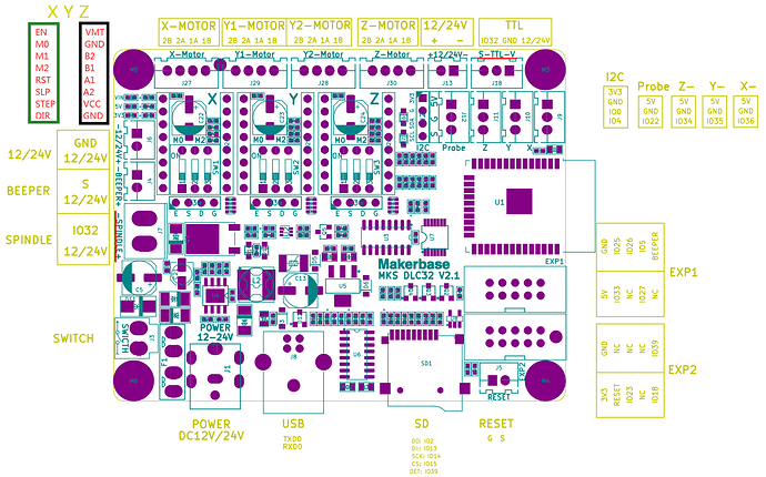
This is from the DLC32 github site that has these schematics and photos.
For reference, notice the connectors on the DLC32 board -Spindle+ are referred to as J7, on the technical board and schematic, the S-TTL-V output is referred to as J18. I tried to mark them with red, but there isn’t much room ![]()
The cpu i/o port on both is 32 (IO32), same signal. Actual pwm goes high by definition as percentage of time in the on state, spindle is the inverted pwm signal. These FET or transistor output configuration, such as here with Q1, are sometimes referred to a sink outputs, as it sinks current or completes the return path to ground.
Now, take a few and look at what they are doing. The pwm goes into the circuit at the LC-0 point.
This goes directly to J18/3 (connector/pin), the laser pwm control. The pwm, going high, also turns on Q1. Q1 completes the ground between J7/1 and power (J7/2).
They are turning the ground connection on/off.
You want a stable ground or signal common reference state.
I guess you can see why I consider this is a sketchy hook up or … lets just say I wouldn’t do it this way.
I think the very design of the controller and it’s labeling contributes to this misunderstanding. It’s marked -Spindle, indicating it’s the negative side of the spindle, so it should be ground… as you can see, that’s not the case. This is typical of many Chinese designs.
Any of this make sense?
I believe the way you’re doing it is the proper approach.
![]()

