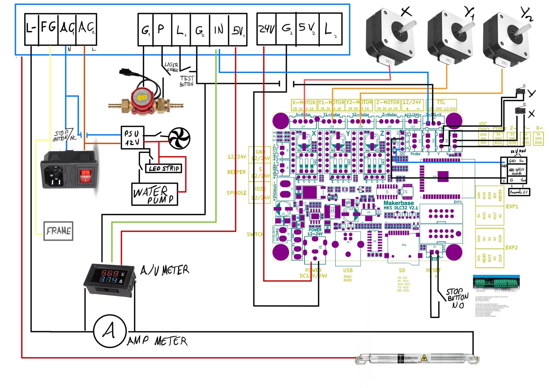
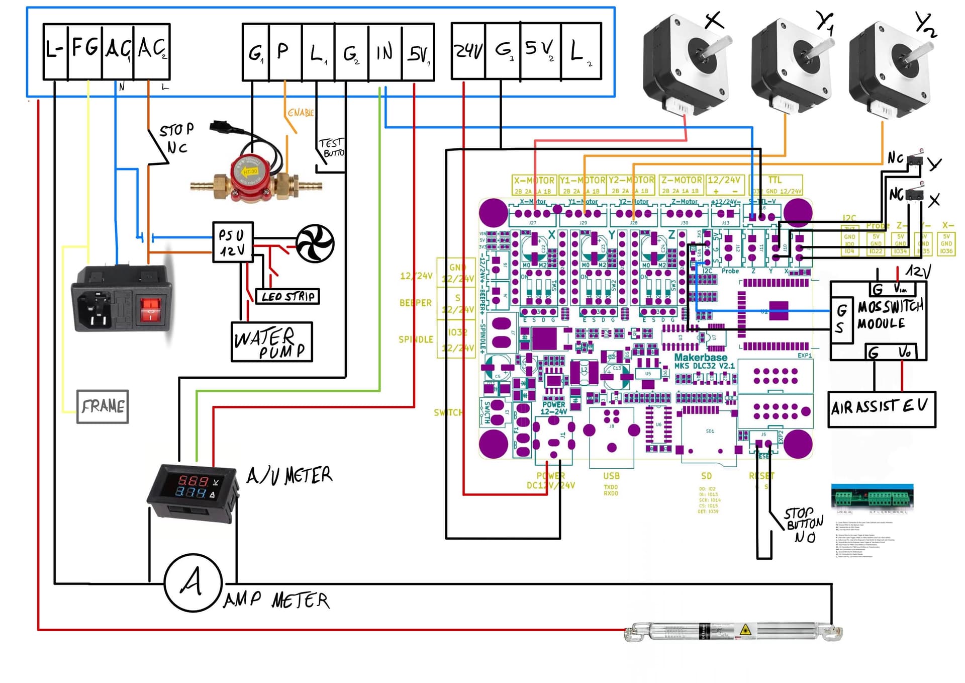
HI! It´s incredible the amount of threads/photos around the internet with wiring options, nothing clear, even contradictory in some cases… so… can anyone help with the wiring? I’m runing a vevor PSU with a 50w CO2 laser and MKS DLC 32, Led strips, EV for the air assist, water pump, extraction fan, water flow sensor, amp meter, and another one with volt meter. So… I didn’t include any variable resistor because I’d like to control the system with lightburn or UGS (Should I add it anyway? In that case, 1k or 10k?). This is my wiring, could someone take a look, do I need to add a resistor somewhere?. If there’s something wrong I’ll update the wiring diagram to help more people in the future.
Thanks!!
I’ll point out a few things, then you can fix them…
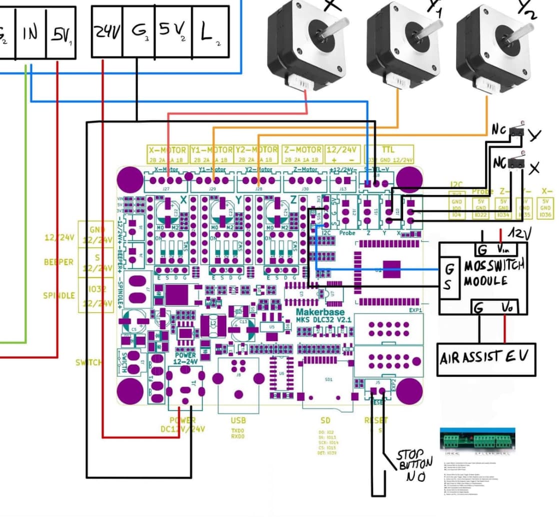
When power comes into a machine, it’s Neutral and Line, the line voltage is the hot side, so you should switch it off on using the L (live) input.
On my OMTech, this is switched in two places, it goes through the E Stop first, then the user has control over the controller powered up and/or the lps.
If you wire it like you have, the live half is always hot. Anything wired to a live voltage will seek its common (N) path, likely through you to earth ground as the Neutral to the machine will be open.
P and L… both P and L need to be grounded for the lps to lase. If the water protect switch you have goes to ground when active, then it’s smart to wire that output to P, which is water protect at the lps.
You could then use the Laser Enable switch to the L input.
On my OMTech, the P input is wired to ground and the coolant status to the controller. If for some reason the cooler failed, the Ruida would shut down the job. Once you fix the issue you can continue.
The drawback of your configuration is the laser quits lasing, but the controller doesn’t know and keeps going, effectively loosing your position and along with the job.
I understand power to the meter, but what is the purpose of using the pwm with the meter?
Are you planning on having a digital and analog meter in circuit for tube current?
Maybe you can explain your thoughts about this sections operation… such as the green line to the pwm.
Stop button is wired to the controller reset… is that what you want? It’ll do a homing cycle, at minimum and not really stop the machine…
I don’t follow what this is supposed to do or of what use it is. You have SDL wired to G on the right and the G of the I2C wired to S on the right …?
If you ohm out the G connections on the lps, I think you’ll find they are all same ground. All of this needs a common ground to operate, so you can probably tie all the black wires together if you wished.
Make sense?
![]()
1 Like
Wow @jkwilborn dude, that was fast, thank you so much for responding so quickly.
You’re right, I had an old teacher who taught us to cut the power at N. I don’t know if it’s an old-school thing or what, but it got stuck in my mind. However, you’re absolutely right, I’ll change it.
As for P, L, and the digital ammeter/voltmeter… I just took the wiring from this configuration:
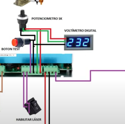
I redrew the P and L wiring to make it clearer in my diagram. Not sure if that’s what you were referring to. Isn’t L the fire test? If it stays grounded, won’t the laser be continuously on? And is there any way for P to also stop the machine’s movement besides stopping the laser?
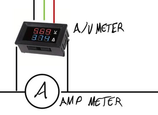
As I mentioned earlier, I took the wiring for the voltage meter from that screenshot. But I can remove it if you think it has no use Having already the analog Ampmeter.
Regarding the stop button, my idea is the following: to use a stop button with both NC and NO ports. If you look closely, the NC is connected to the power input for the whole system, and the NO is connected to the reset on the MKS DLC32. My idea was to cut the power to the entire system while simultaneously resetting the MKS board, in case the capacitors retain enough energy to power the motors for a fraction of a second. I’m not sure if that makes any sense…
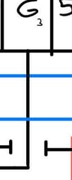
As for the I2C, I’ve redrawn it. I didn’t expect the image to get compressed so much; it’s actually connected to a MOSFET module that activates the air assist EV.
Yes, I know they share G, but my idea was to try to make the diagram as close to the actual wiring as possible and structure it in “blocks.” But for this purpose, I’ll simplify it as you suggested.
I’m attaching V2 of the wiring diagram, hopefully, this is the last one, so I won’t take up more of your time, jeje.
Sorry about the dealy, I have doctors appointments that take me away from this stuff… not to mention I’m a bachelor this week.
With this configuration the PSU/Fan/LED and water pump will be on anytime the machine has power.
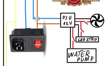
On mine, Control Switch is the power to the machine, Laser Switch goes to the lps.
What you have as enable, is the switch within the sensor, you don’t need another switch.

What are you expecting from the green line to the A/V meter? This is pwm, so I don’t know why you have it wired here.
Hope this makes sense?
![]()
1 Like
Don’t worry, mate, I hope it’s nothing serious and everything is okay, and congratulations!!
First of all, I’ve seen your profile and would like take a few seconds to thank you for your contribution to the community, that’s dedication.
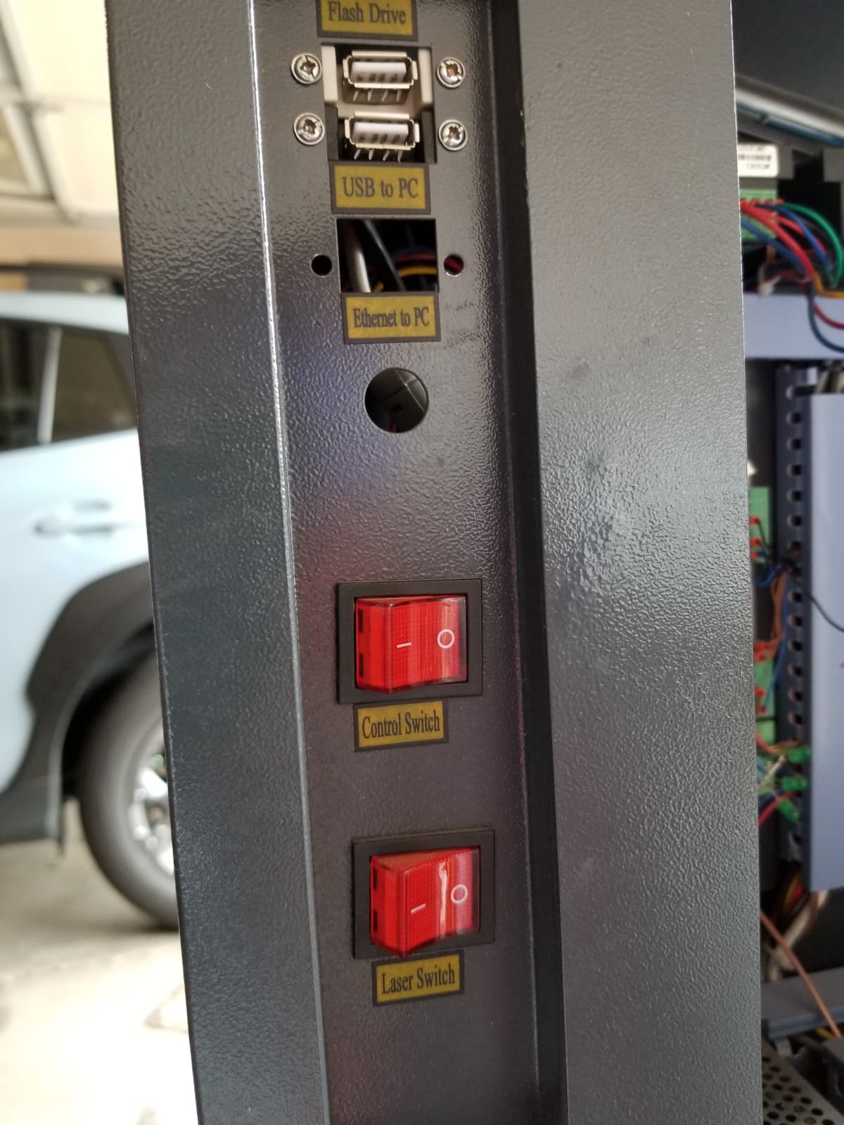
It’s true I haven’t properly marked it, but in the following images you’ll understand better:

As you can see, my main switch is located at the beginning, on the same input socket with a built-in fuse, so turning on that switch would power both the laser power supply and the 12V one. If you look closely, between the 12V PSU and the extraction system, LEDs, and water pump, there are normally open switches that I’ve labeled as S1, S2, and S3 (latching switches) because I want to control them manually, as you can see on my control panel:

Regarding the ‘enable,’ it’s actually ‘laser enable’ and is controlled by a rotary switch. It’s an extra safety system that allows me to disable the laser without deactivating the controller, touch panel, and motors.
And coming back to the voltage meter… I don’t have an answer for you, I hope you can shed some light on this because I took it from the following diagram from the internet:
I’ve opted to omit the digital A/V meter and stick with the analog ammeter, but I’d like it to be clear in the diagram in case it helps someone in the future.
I assume the rest of the wiring is correct? What concerns me the most is this part:
I want to control the laser’s power from the software without needing to use a variable resistor… I’ve seen diagrams with 1k potentiometer and others with 10k, which one would be correct if someone wanted to implement that wiring option?
Thank you again.
It’s confusing by the way it’s drawn.
If your stop switch is open, then nothing gets power even if the switch/fuse assembly is enabled. If the stop switch is is the emergency stop … that should work.
This is what you say you don’t want, it bypasses the software power settings. Then uses the pwm to turn it on/off at whatever the pot is set. You get power/time which is digital…
I find a 5K very functional. It’s only used as a voltage divider. 5V/5K is 1mA.
This sets the current limit…
Make sense?
![]()
Yeah… Sorry, once I get the setup clear I’ll make a proper diagram with my setup.
Yeah, the stop button is wird at NC to cut power but I don’t know what approach I’ll take… I dont know if I’ll use the stopt button to cut power or tu activate the reset function of the mks dlc32. The way it’s wired right now, the fuse/switch will cut all the incoming power.
I know, that’s why I only took the wiring from the A/V meter in that diagram, but I have removed it since I’m not implementing a potentiometer for now. As I mentioned, my intention is to control everything from the software.
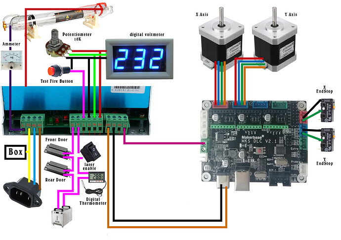
And going back to the control wiring topic, I saw that you mentioned this thread in another discussion. I noticed that in the same thread, another person attached a diagram that worked for them:
and now I’m even more confused, it’s quite different from mine. It uses the G output of the spindle, which is used in other diagrams that opt for the use of a potentiometer. So, what is the correct way to wire that part (the TTL-S control)?
Using the boards reset implies you know the problem isn’t the board, electrical or something else running off mains power…
The purpose of an emergency stop is for catastrophic failures, such as fire, electrical or mechanical failures.
If your control board failed (maybe burning), the switch would do nothing and still allow mains voltage into the machines supplies.
Good — cut all power coming into the machine, ahead of the power switch.
Use one or the other… probably didn’t have to mention it but I did.
Don’t be…
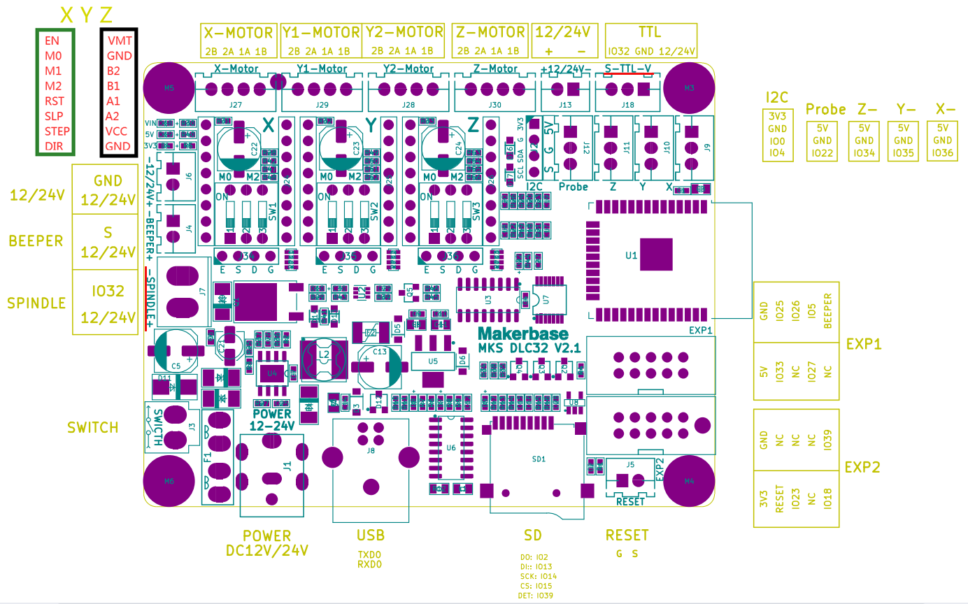
This is from the DLC32 github site that has these schematics and photos.
For reference, notice the connectors on the DLC32 board -Spindle+ are referred to as J7, on the technical board and schematic, the S-TTL-V output is referred to as J18. I tried to mark them with red, but there isn’t much room ![]()
The cpu i/o port on both is 32 (IO32), same signal. Actual pwm goes high by definition as percentage of time in the on state, spindle is the inverted pwm signal. These FET or transistor output configuration, such as here with Q1, are sometimes referred to a sink outputs, as it sinks current or completes the return path to ground.
Now, take a few and look at what they are doing. The pwm goes into the circuit at the LC-0 point.
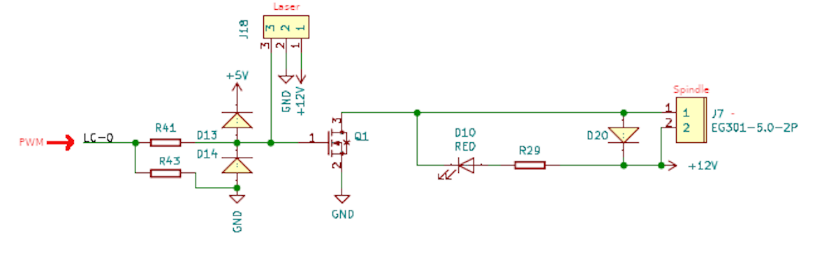
This goes directly to J18/3 (connector/pin), the laser pwm control. The pwm, going high, also turns on Q1. Q1 completes the ground between J7/1 and power (J7/2).
They are turning the ground connection on/off.
You want a stable ground or signal common reference state.
I guess you can see why I consider this is a sketchy hook up or … lets just say I wouldn’t do it this way.
I think the very design of the controller and it’s labeling contributes to this misunderstanding. It’s marked -Spindle, indicating it’s the negative side of the spindle, so it should be ground… as you can see, that’s not the case. This is typical of many Chinese designs.
Any of this make sense?
I believe the way you’re doing it is the proper approach.
![]()
This topic was automatically closed 30 days after the last reply. New replies are no longer allowed.