I understand.
I think you are confusing yourself more trying to associate different controllers with their pinout. You seem to understand connection of the motors to the board. It sounds like, for you, is how you wire the DLC32 to the laser power supply (lps).
I’d think you’d do better if you just look at how these control signals work and use that information to wire you new board, instead of trying to take into account how these other boards interface. The Nano is an amazing board, but is only a MC-51 controller (8051), which I used back in the mid 80’s… so it’s an amazing engineering creation as it’s implementation within the Nano.
Keep in mind these are generally used for driving digital devices such as the diode laser module most people have. A glass dc excited co2 tube is an analog device, which is what the lps is designed to use.
Lets start with how the lps functions. The control pins are H, L, P, G, IN and 5V
| LPS designation | Function | Active state |
|---|---|---|
| H | Laser Enable | High |
| L | Laser Enable | Low |
| P | Water Protect | Low |
| G | Ground | Signal Common |
| IN | Current Limit | DC Voltage |
| 5V | 5V limited current | N/A |
Using either H or L, these enable the lps to lase at the current set on the IN pin.
Even though you’re applying a pwm signal to the IN input, the lps filters this internally and produces a 0 to 5V DC current control voltage. Some machines like my Ruida also have an analog output to do this directly with DC. But there is no difference as far as the lps is concerned.
P is water protect, this should be pulled low when the coolant is circulating properly. It’s usually done with some type of switch connected to you coolant tube or system. Yours is probably already wired this way… I would hope.
G is a common ground. You should be able to wire any ground to any other ground… You can’t measure only one wire with a meter, you must have it relative to some value, hence a common ground and why you have two leads on a voltmeter.
The last one is 5V, pretty self explanatory, but it’s a very limited current source of around 20mA.
The normal use of IN and L is the controller sets a voltage (or pwm) value of between 0 and 5V, related to 0V being 0 percent power and 5V being 100% power.
When it needs to lase, the controller enables the laser via H or L becoming active. Most of the dsp I’ve looked at produce a pwm continuously when it runs a layer and L becoming active enables it to fire at the IN determined maximum current.
Since the DLC32 does not have a Laser enable (H or L) we can use that to run through a manual switch (your ligar aluz) for the operator to enable the laser. If the laser is enabled, it will only lase when there is a pwm signal.
I hope this make sense.
You can drive the glass tube as a digital device. If you run the pwm from the controller to the H input then use a 5K pot as a voltage divider to set the IN voltage manually. I think it’s bad for the machine, at least the tube because you are now turning the tube on/off at the manual set current level… just like a diode.
The 5V pot usually uses 5V from something like the lps, since it’s only drawing a 1mA.
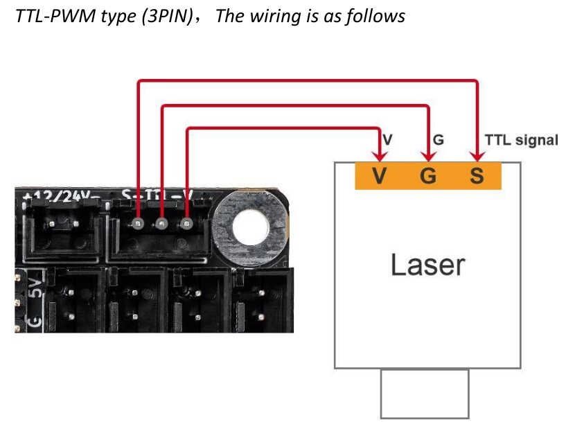
From the DLC32 manual, the S output should be all you need as the lps should already be grounded to everything else. You have no use of the supply voltage here.
Let me know if I confused you more or?
Here’s a link to someone else’s issue with their DLC32… maybe it will help.
Good luck
![]()