Hi all! I’m in a bit of a pickle! The M2 Nano on my K40 just said goodbye to one of the drivers while cutting a big order. I do have a Two-trees Ts2 with a MKS DLC32 in it and am looking for a reliable resource to adapt this board to my K40 as fast as possible! My LPSU is a bit different than what I am seeing in some tutorials, it has 2 green plus instead of 3, and I am not completely sure of how I must wire the laser negative to my board. Can any good soul please direct me to a post or reliable source so I can continue working?
I know it’s not as simple as dropping a new Nano, that’s why I need guidance, just so I can do it right in the first try and not damage other components. I live in Brazil and here we don’t have much options for parts suppliers, if we don’t but from China, that takes a couple of weeks, we need to pay a hefty premium to whomever have the parts here locally
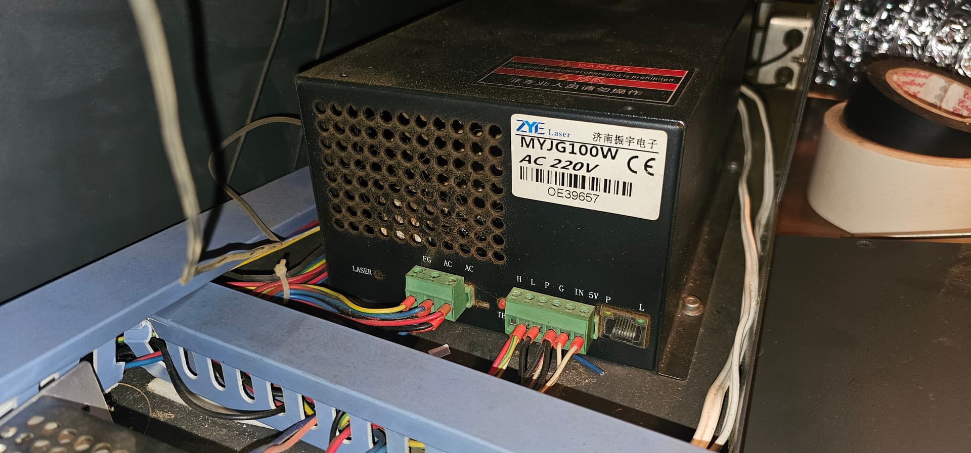
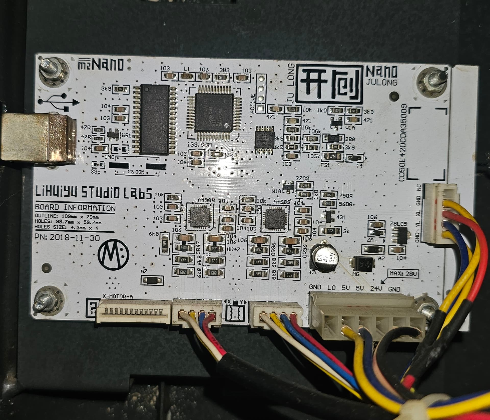
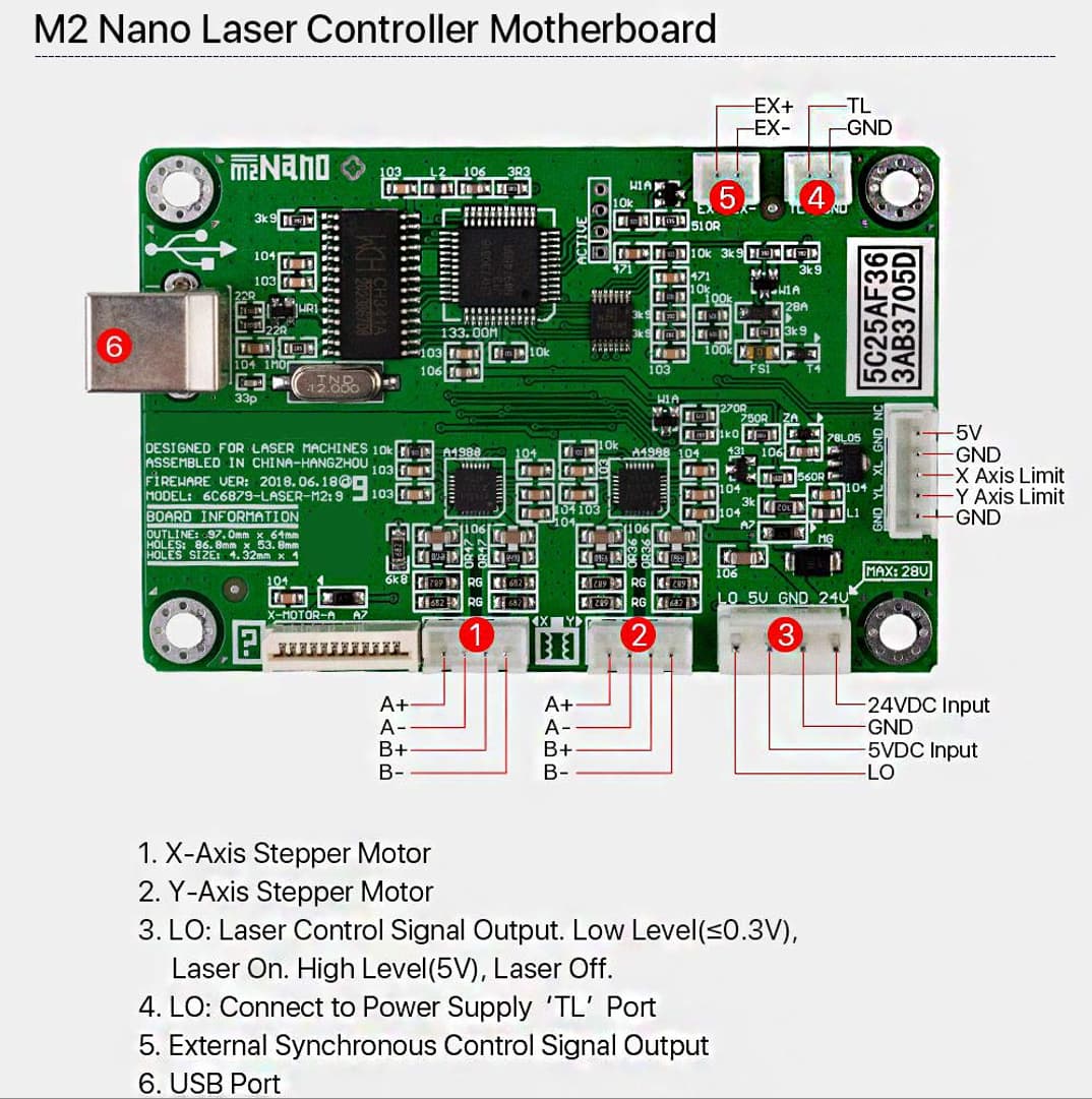
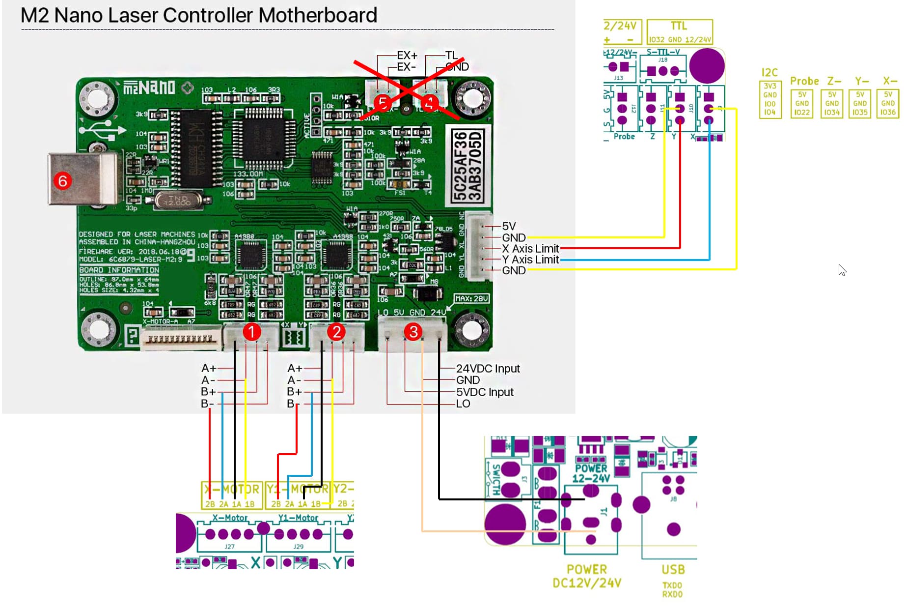
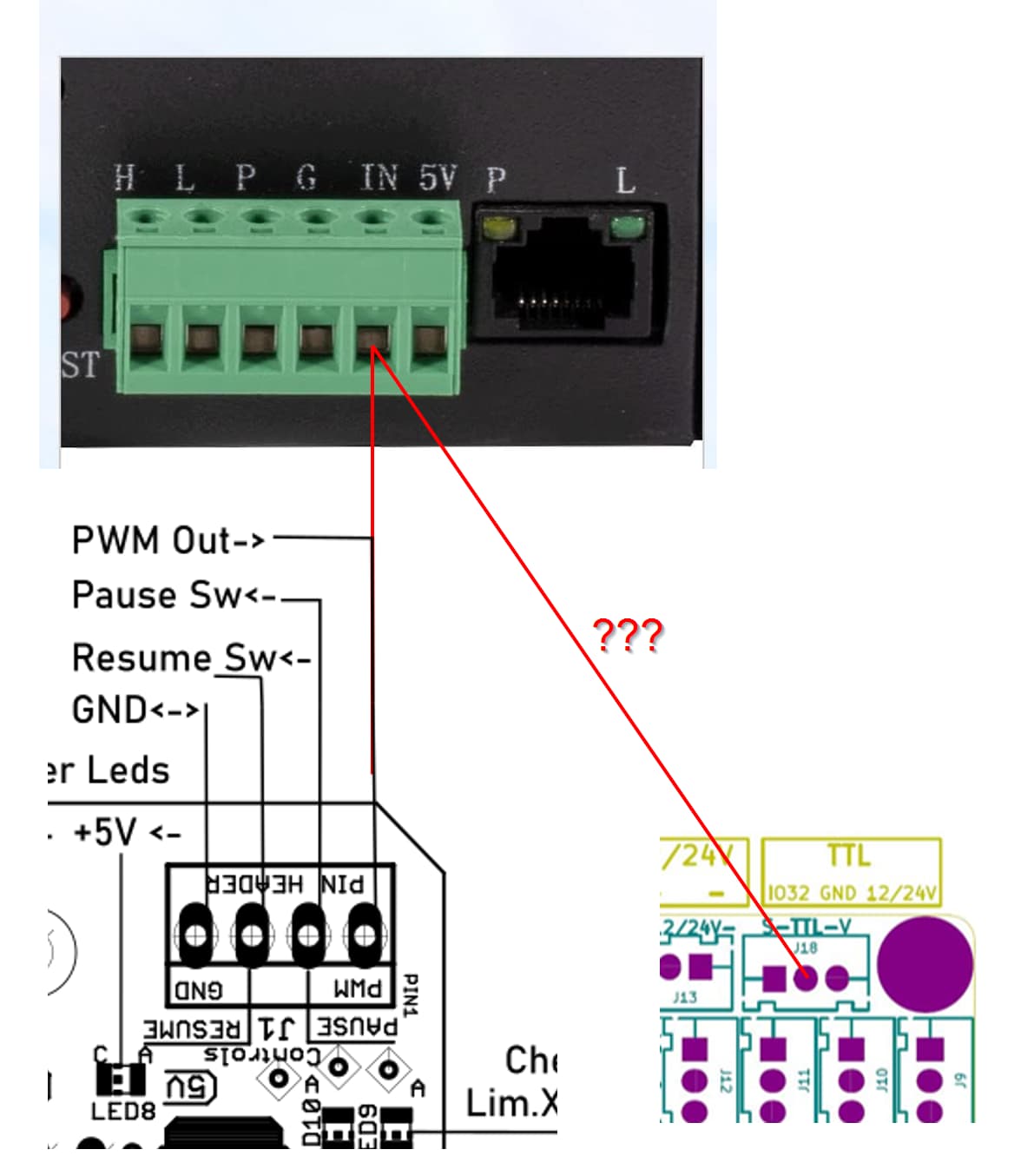
From what I can see on a picture I took from my board a while ago, there are only 4 connector in use, with a big one not completely used, it has 6 pins but just 4 are in use.
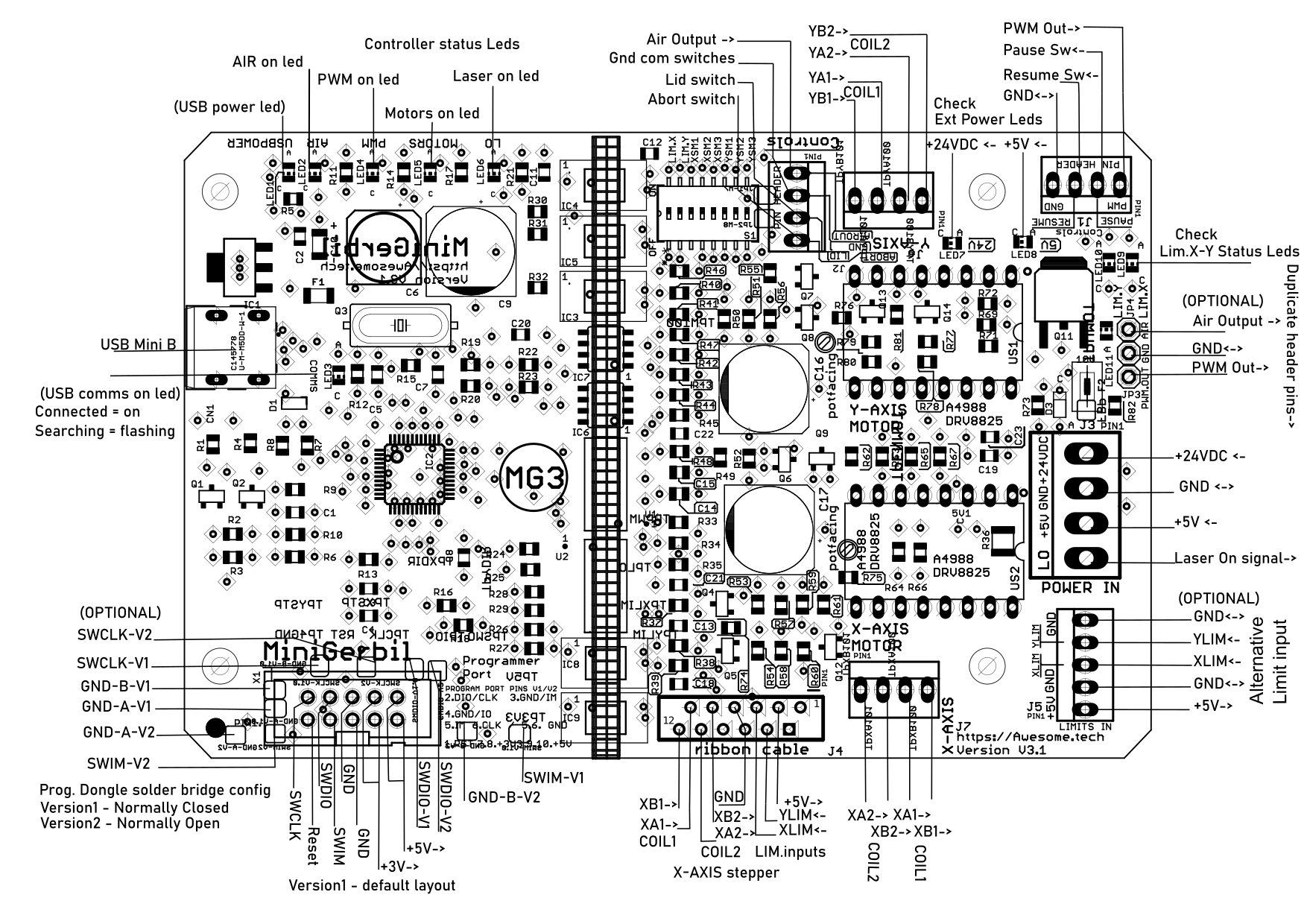
While researching I found an installation video from Awesome’s Tech Mini Gerbil, and they have just a single wire going from the LPSU’s IN to the board’s PWM Out.
I have found several different cases of people trying to do the same conversion as mine but several different directions with differente rates of success.
Does anyone know if just connect the LPSU’s IN to the DLC32’s TTL pin would be enough?
I think you are confusing yourself more trying to associate different controllers with their pinout. You seem to understand connection of the motors to the board. It sounds like, for you, is how you wire the DLC32 to the laser power supply (lps).
I’d think you’d do better if you just look at how these control signals work and use that information to wire you new board, instead of trying to take into account how these other boards interface. The Nano is an amazing board, but is only a MC-51 controller (8051), which I used back in the mid 80’s… so it’s an amazing engineering creation as it’s implementation within the Nano.
Keep in mind these are generally used for driving digital devices such as the diode laser module most people have. A glass dc excited co2 tube is an analog device, which is what the lps is designed to use.
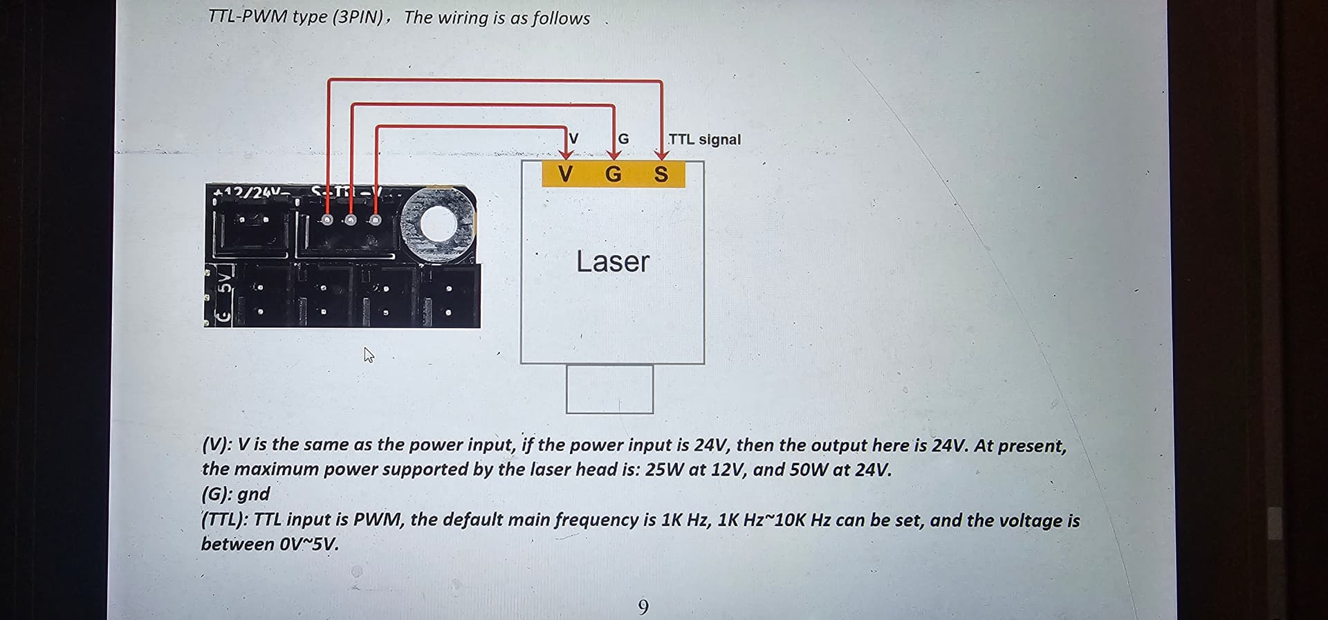
Lets start with how the lps functions. The control pins are H, L, P, G, IN and 5V
LPS designation
Function
Active state
H
Laser Enable
High
L
Laser Enable
Low
P
Water Protect
Low
G
Ground
Signal Common
IN
Current Limit
DC Voltage
5V
5V limited current
N/A
Using either H or L, these enable the lps to lase at the current set on the IN pin.
Even though you’re applying a pwm signal to the IN input, the lps filters this internally and produces a 0 to 5V DC current control voltage. Some machines like my Ruida also have an analog output to do this directly with DC. But there is no difference as far as the lps is concerned.
P is water protect, this should be pulled low when the coolant is circulating properly. It’s usually done with some type of switch connected to you coolant tube or system. Yours is probably already wired this way… I would hope.
G is a common ground. You should be able to wire any ground to any other ground… You can’t measure only one wire with a meter, you must have it relative to some value, hence a common ground and why you have two leads on a voltmeter.
The last one is 5V, pretty self explanatory, but it’s a very limited current source of around 20mA.
The normal use of IN and L is the controller sets a voltage (or pwm) value of between 0 and 5V, related to 0V being 0 percent power and 5V being 100% power.
When it needs to lase, the controller enables the laser via H or L becoming active. Most of the dsp I’ve looked at produce a pwm continuously when it runs a layer and L becoming active enables it to fire at the IN determined maximum current.
Since the DLC32 does not have a Laser enable (H or L) we can use that to run through a manual switch (your ligar aluz) for the operator to enable the laser. If the laser is enabled, it will only lase when there is a pwm signal.
I hope this make sense.
You can drive the glass tube as a digital device. If you run the pwm from the controller to the H input then use a 5K pot as a voltage divider to set the IN voltage manually. I think it’s bad for the machine, at least the tube because you are now turning the tube on/off at the manual set current level… just like a diode.
The 5V pot usually uses 5V from something like the lps, since it’s only drawing a 1mA.
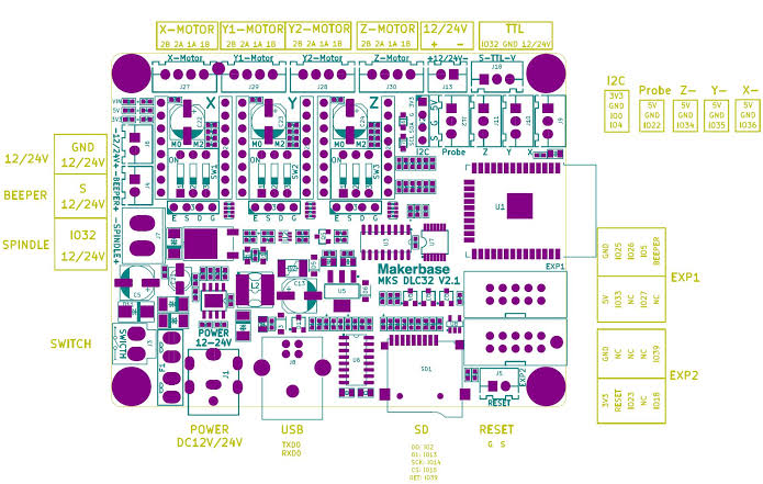
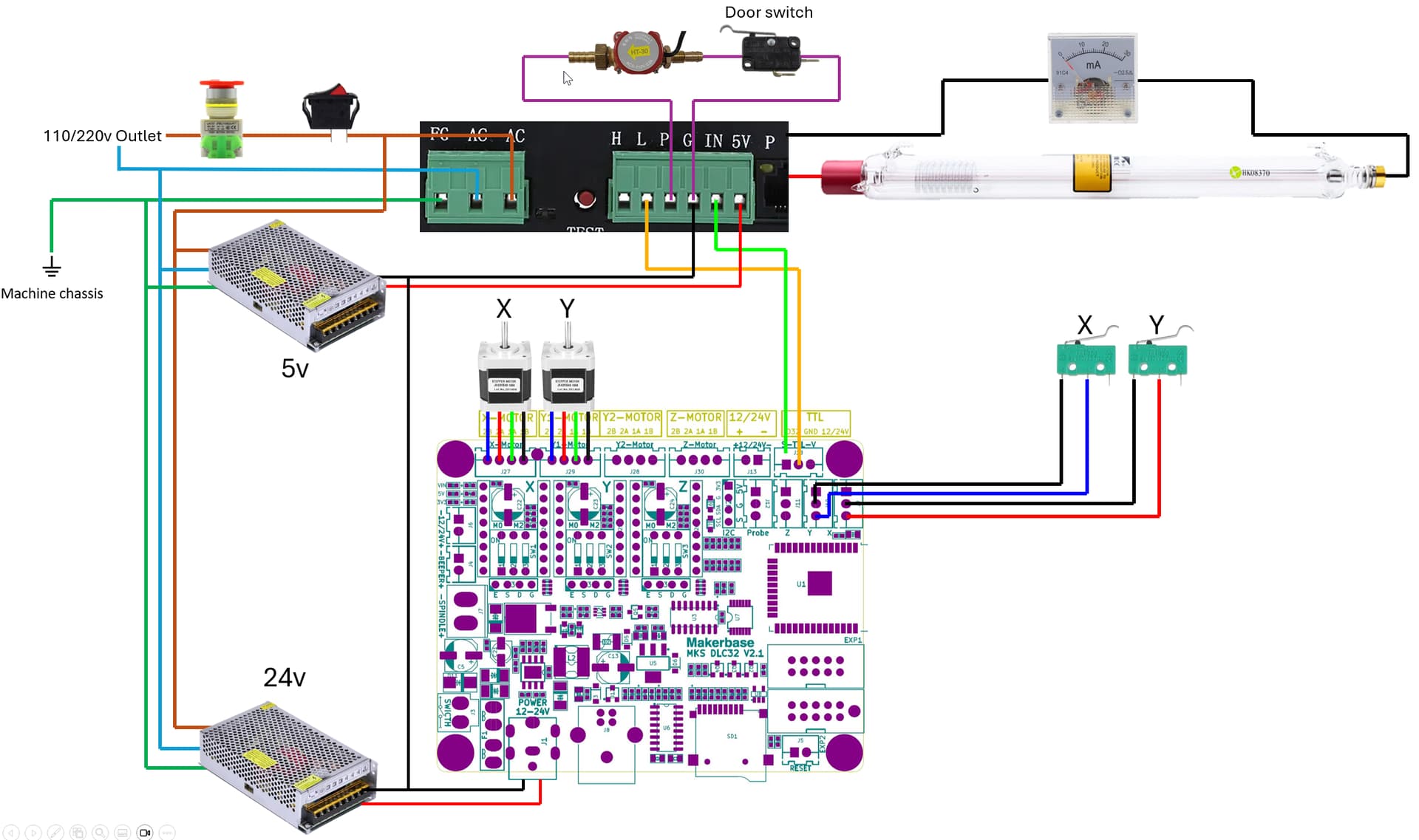
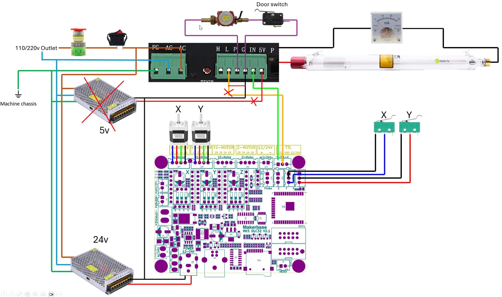
From the DLC32 manual, the S output should be all you need as the lps should already be grounded to everything else. You have no use of the supply voltage here.
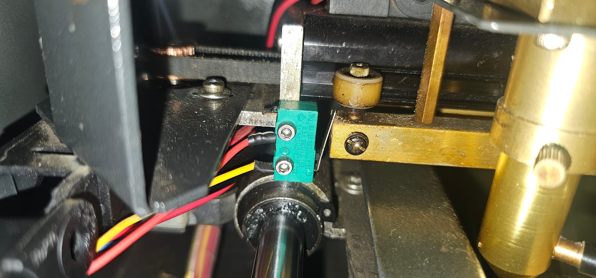
I watched a video from a guy upgrading a Monport machine with a GRBL board, also from Monport, and he had to change the endstop cable positions. The endstop has 3 tabs and by default the outer tabs are used. The board does not detect the endstop in that configuration, same happens with the DLC32 board, after changing like illustrated below, Lightburn detects the endpoints.
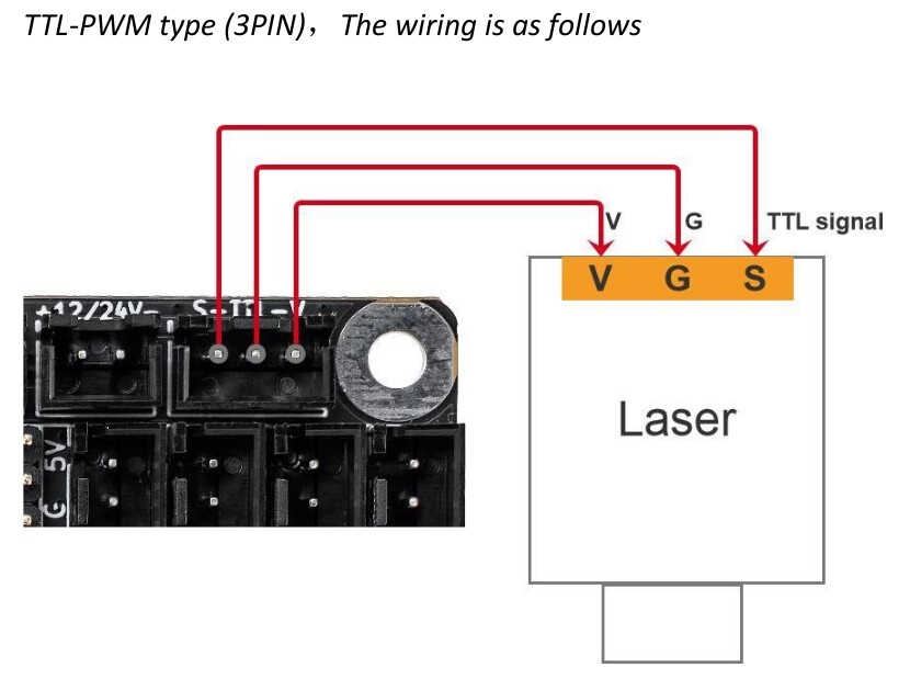
Actually the connector is labeled S - TTL - V, meaning it’s a ttl signal level (0 to 5V) signal, and that S is signal or pwm, center is ground and right is supply voltage to the led module…
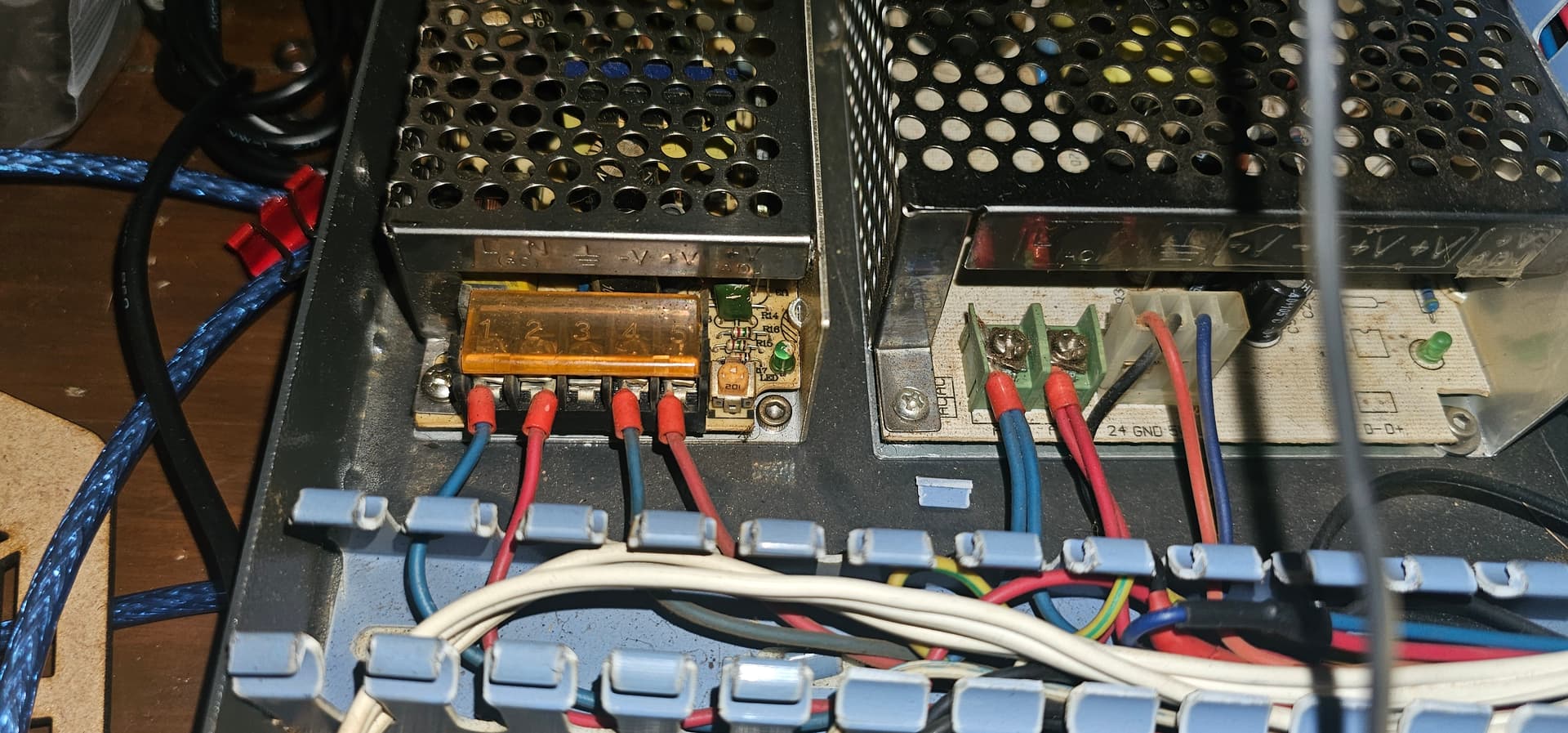
My K40 came with a pretty low quality dual voltage (5v/24v) power supply, so I just bought individual PSUs. I also have the LPSU LCD screen on it’s way!
I hope this helps lots of people, If possible/needed we could pin this somewhere so it’s easier for people to find!
The items with a red x are not needed. The red line from L to G will do the same thing. I’d suggest you run it through a laser enable console switch that’s already mounted on your console.
There is no need here for a 5V supply. The 5V line of the lps is an output, not a a required supply input.
In reality, the Chassis ground is (should) be the same as the board/power supply ground in your system. The black line (ground) is connected to all components, so it should be fine.
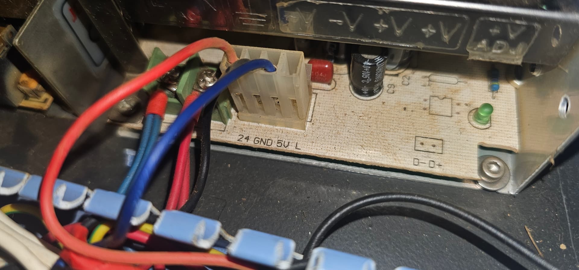
About the 5v volts PSU, I was checking the original wiring and it makes sense. Looks like the M2 Nano don’t have a 5v voltage regulator like the DLC32 does, so it needs that 5v input. But also, the same 5v goes to the red dot on the laser head and there was another wire but I can’t recall what it was connected to.
Looking at the pictures I took before, that LPSU 5v was going to the front panel, so maybe it was feeding it’s board.
Regarding the TTL, are you sure? The laser was just refusing to fire and it just worked when I plugged it to the L. But it does make sense since there’s a single ground for the whole system and the DLC32 is plugged on it.
That wasn’t in your diagram, so you may need to come up with 5V. I’d try and use the 5V off the lps to drive the led pointer…
This is what I’ve seen, but Don’s site claims they can supply 1A… however this is a K40 site and this type of lps may have more power to drive the nano boards.
These supplies require L to be low and a voltage or pwm applied to IN. Any communications addressing the lps in this situation requires you to advise us of the state of both L and IN.
Although most of us understand what’s happening, we are not mind readers, when you state: worked when I plugged it to the L … joyous, but I have no idea what you plugged in what to make it seem like it’s operating …
Off hand, lacking data, I’d have to say you were not enabling the lps, meaning L wasn’t being held low.
There’s a picture of a seller at aliexpress that states that the current at the 5v output is 50mA. But I’ll try anyway, if it works I’ll just return the PSU
I’ll try again with your suggestion of bridging L and G
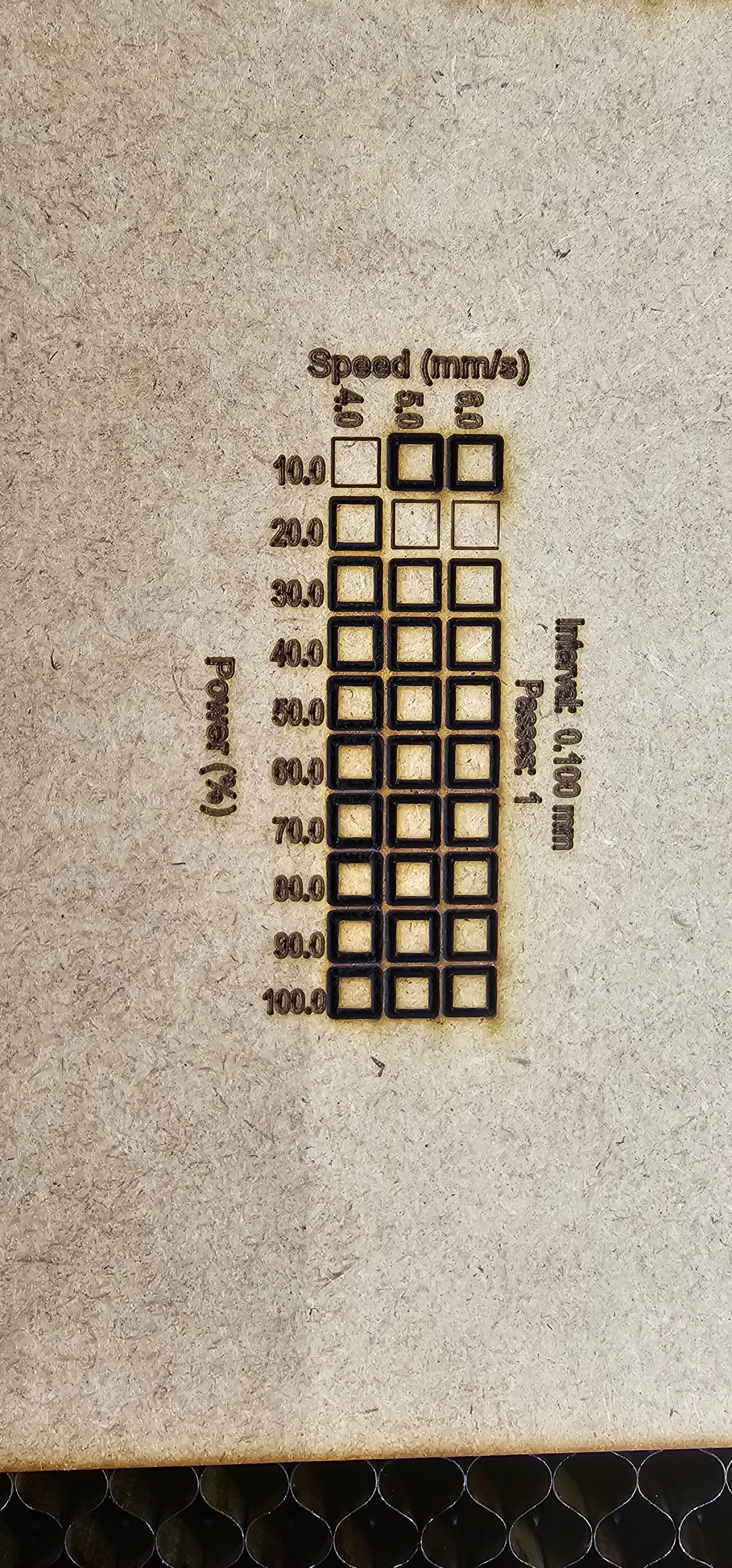
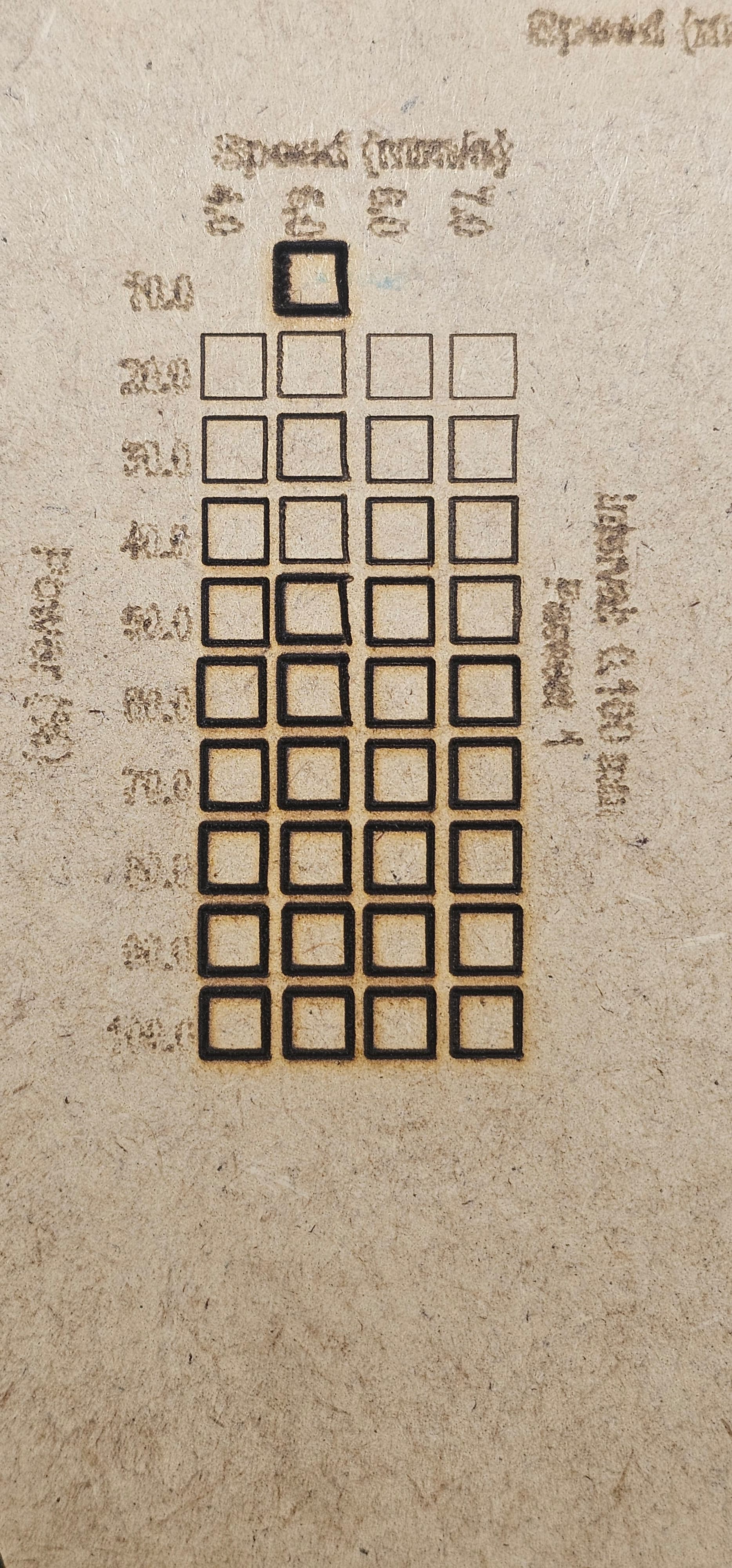
So, a new challenge enters the stage: the machine won’t cut as before anymore! I did and redid the laser alingment, cleaned everything, rechecked the connections, etc. It is just making lots of smoke and won’t cut the 3mm MDF that would have no problem at 60%/6mm/s. Not even at 100%/4mm! Does anyone that also made the conversion resolved it? My $28 is already at 1000, i don’t believe that’s a firmware issue, since the board came from a diode laser machine, not from a CNC milling machine.
PWM frequency, is usually referred to as the period.. PWM is based on how long the complete cycle is (the period), not the frequency, albeit they are inversely related.
Neither should effect your machines operation. I have no idea what it’s used for in your machine, that would end up in your lap to figure out.
Someone here might know, but it won’t change anything on your laser if it’s the pwm you’re changing.