DIY Rotary not working as it should

Hello,

first of all, sorry for my bad english, i am from germany… :slight_smile:

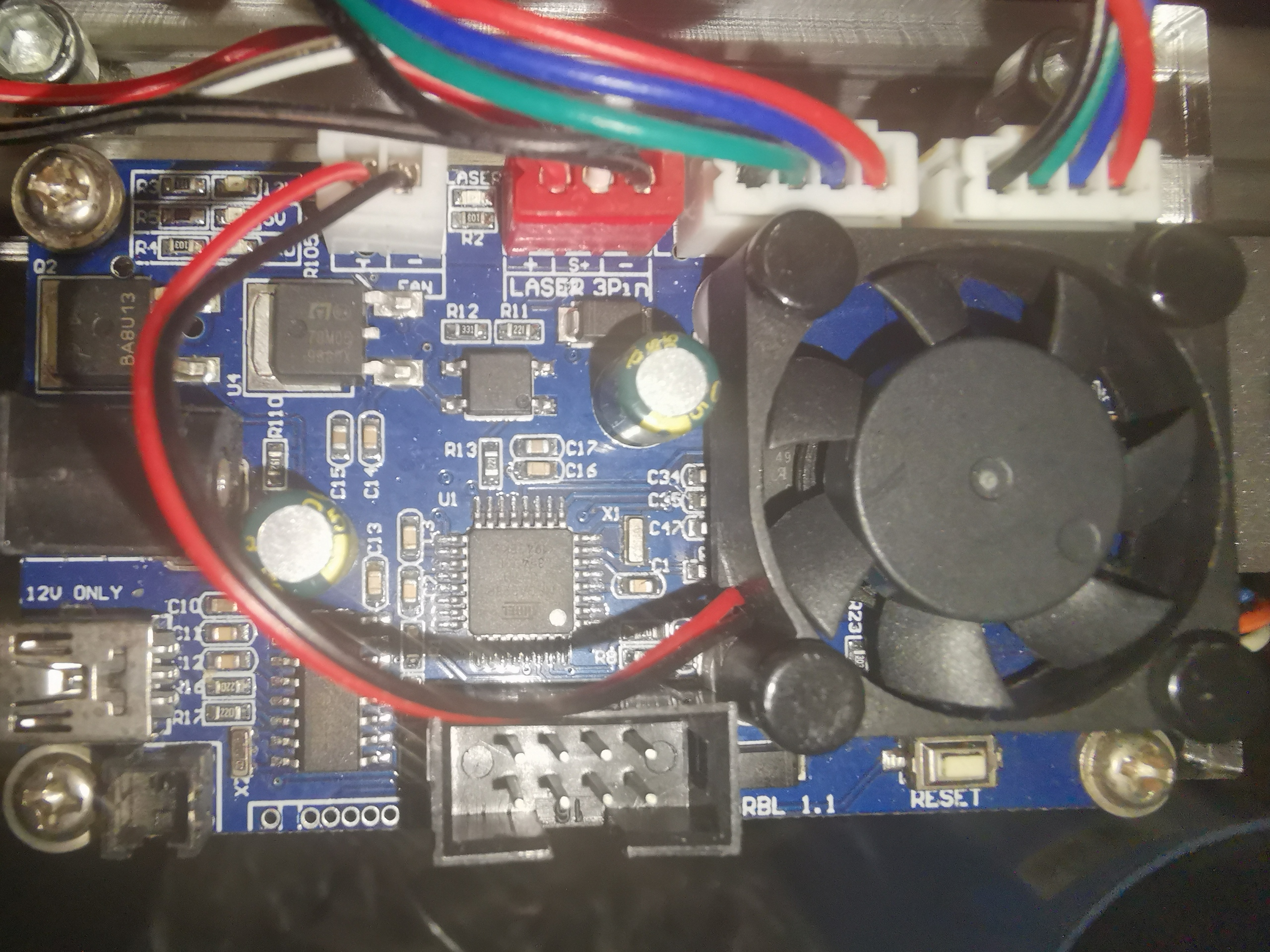
i tried out Lightburn and build myself a DIY Rotary for my 7W Chinese Diode laser. It is a simple Roller Rotary, i use it on the Y-Axis of my Laser, because the Board only have 2 Axis Connectors. It is a very simple A3 Laser. I tried to configure the Rotary Settings for my Rollers and the Stepper but it will not work correctly i think.

What i did so far:

  1. i placed a marker on top of the rotary wheel. All the manuals in the web and youtube says i must find out the right Steps per Revolution for my motor, but in the newest Version of Lightburn there is only the Option “mm per Rotation”. So i tried some different values, until the Wheel is turning one time around and stop again at the Marker. When i use the Test-Button in the Rotary Window, it rotate 1 Revolution, stops and go back and stops again on the Marker. Everything okay, i needed the mm Distance of 40,20mm for that.

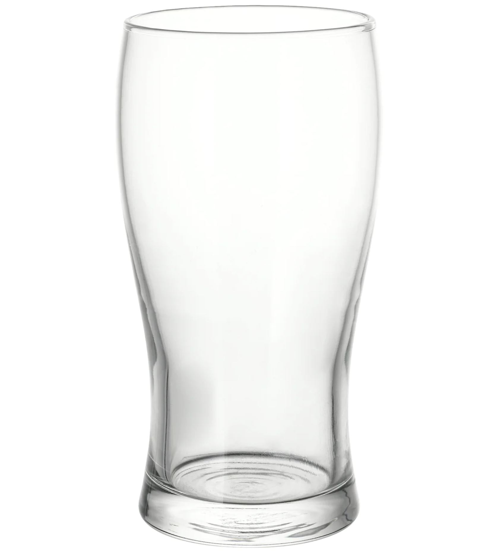
  2. i measured with a caliper the diameter of the Rollers. It is exactly 39,50mm. I put it in the rotary Settings and put on a drinking glas on the rollers. On that point where it has contact on the Wheels it has 52mm in Diameter.

But here is the first problem, when i now press the test button and put a marker on the Glas, it will not stop on the marker. I tought i must measure the Object Diameter and put it into the Settings but i noticed the Object Diameter does nothing.

So i tried around and found out when i change the mm per rotation 74mm, the marker on the Glas does 1 Revolution. So do i must edit the Settings everytime i put on an Object with a different Size?

But the next Problem coming here, i put on the Workspace a Box with the height of 163.363mm. It should be the Curcumference of the Object, so 1 wrap arround, when i understand it right?! But when i use the click on page to travel method and click the end of that box, the rotary turns 4 times and stop on the marker. Why 4 Times?? And there is the Problem now, when i put an Object on the Workspace that have exactly 30mm for example, it comes out very stretched.

I tried so much stuff now, i placed so many different values in the settings, sometimes the wheel does turn 1 revolution, one time the glas do 1 revolution but whatever i try, when i put an object on the workspace with specific measurements, it comes out streched.

The only thing what worked so far for me is to place some paper arround the object, laser a box of 30mm on it and measure it with a tape measure. If it is to long, i reduce the mm per Rotation Value, if it is to short the opposite. I do it so long until the box is exactly 30mm on the glas. With that value then i can laser my Logo or something on the Glas. And it comes out correctly. But it is very complex to do so. Isn’t there a easier way for me? What i must put into the mm per Rotation Box? The Value for 1 Rotation of the Rollerwheel or the Object to laser??

I hope someone can give me some hints here, i don’t know what i’m doing wrong…

Thank you very much!

The ‘Test’ function on a roller rotary does one rotation with the roller, not the object. If you set the value so that the object does a full rotation, the results will be wrong. If you put the mm per rotation value back to 40.2mm the rest should work as expected.

The reason you don’t get ‘Steps per rotation’ is that the settings are different for different controllers. DSP machines have hardware support for rotary, so they use motor steps. GRBL and other GCode controllers have either a rotation dedicated axis (360 degrees per rotation) or a linear axis, like Y, where you have to send a normal move in mm to rotate.

Ah okay, that brings some light in the darkness… thank you very much for your answer.

So, i tried already to set it to 40.2mm, so the Roller Wheel turn 1 times. But when i do the Box Test and try to Laser a 30mm Box on the Glas, it turns out exactly 40mm. Is that normal? Is that maybe because of the Warp? But when i put on a Tape measure, should it not be 30mm?

There are very few people using the rotary function without a dedicated rotary axis, so it’s quite possible that the scaling is incorrect. I’ll have a look.

Thank you, that would be nice. Until that i will just use the method i described in my first Post to calibrate my Rotary Device. Maybe it would be better to upgrade to another Board with more than only a X and Y Axis Connector.

It actually does work as expected for me when I frame.

  • Make sure that you have the rotary switch enabled when you leave the Rotary Setup menu.

  • Make sure you are using ‘Current Position’ mode for the ‘Start From’ setting, otherwise it will rotate first to the start point, then frame, then rotate back.

1 Like

Yes i checked both, i set the Box Origin to XY 0,0 so it must not Travel to a starting Position. But the cutted Box is 40mm, so not the lasered Box is offset, the whole Box is too long. The Rotary Switch is enabled. But the Size of the Object that is on the Rollers does not matter?! Like i said, it is only possible to get exact 30mm lasered when i reduce the 40.20mm mm per Rotation so about 30mm. I do not understand where that 10mm Difference is coming from.

The important number is the mm per rotation. On mine, when I set that number to 40.5mm (using a Cohesion3D board) it does one complete rotation and comes back again. That’s step one.

Step two is setting the roller diameter. This is used when computing how far to move the rollers for a job, so both of those numbers have to be correct. The object diameter value is only used to compute the object circumference in case you need it to figure out the job height - it doesn’t affect the outcome of the job when in roller mode.

Have you set the roller diameter value correctly as well?

What Board that is i can not tell you, i never found that one on Google. It might be a very basic and cheap one, even in the manual on the Pictures it is another Board.

That is it:

So of course i must plug out the Y Stepper and plug in the Rotary. The Rotary i build is the Design from that Link: https://geeksmithing.com/rotary/
So a very Basic one.

The Roller Wheels i printed on a FDM Printer and Put on a Rubberband on it. I measured it between my Caliper, to get the Diameter of it. So i only need the Diameter of ONE Rollerwheel, right? Both Roller Wheels are the same Size. The Distance from Top to Bottom of the Roller Wheel is exactly 39.50mm. So that should be the Diameter, if i am correct.

So i set a Marker on top of the wheel and found out that 40.20mm is the Distanz for “mm per Rotation” that is needed that the Marker does one Revolution, and stop again on the same Spot. I used the Laser Test for that. Fired it on the Roller Wheel, placed the Laserhead exaclty on the marker, testet the Distance and activated the Test Laser again. And it hits the same spot again.

Then i put the Glas on, put a 30mm box on the Workspace, set the Laser to XY 0,0 and moved it by hand to the starting Point on the Glas to laser. I put then the 30mm Box with the place on left down of the Page function so the left corner of the box sits exaclty on 0,0. When i then hit the Frame Button, the Laser begins direclty to draw the Box… then i engrave with some more power to have an mark on the paper arround the glas and when i measure that box now it has exactly 40mm… but should have 30mm, when i am correct and did everything correctly so far…?!

Is the glass tapered?

Yes, it is not the same Diameter on top and bottom. It looks a little bit like that:

The Rollers sit on the bottom Part of the Glas. The Box to test will be lasered on the wider Top Part. But does it matter in that case? Because i can not set any Object Diameter in Lightburn?! I can not place it on the wide Area, because that the heavy Bottom will tip over…

That all does not much sense for me, when i think about it. How will Lightburn know the Diameter of the Object that is on the Rotary? The Ratio of the Movement is not 1:1 when i am correct? So, without any Value for the Diameter of the Object, the traveled Distance on the Surface is always different, when it is not exactly the same Size as the Roller Wheels?! When i put a small Object on the Rollers like a Broomstick, it will spin much faster 1 Revolution then a bigger Object like a Glas. Or a extreme Example, we put on a Rocket on the Rollers, to move it So Lightburn know how much to turn the Roller for 1 Revolution, but Lightburn das not know how far the Roller Wheel must move the Object, to Laser exactly an Box with 30mm width.

The same thing is beeing showed in that Video: https://youtu.be/V069YwqK3XQ?t=229 where he explaining how to calculate the Ratio between the Roller Wheel and the Object. So maybe that is missing here…? Or maybe i am complete wrong…

The different diameters are the problem. If you were burning the logo at the bottom, where you are driving the glass, the logo would be the correct size. If you turn the logo 180 degrees, and turn the glass so the wide part is being driven, that will give you the correct output size as well.

The math works because LightBurn knows how large the roller is (the circumference is calculated from the roller diameter). One complete turn of the roller moves the surface of the object being engraved by the circumference of the roller, and that surface distance is what you care about.

In all of your examples, the part you are missing is the size of the design. When you are in the rotary screen you enter the size of the object (the diameter) and LightBurn shows you the circumference. That number is what you use to decide how large to make the design so it will fit on your object.

I tried now just for fun the Formula in the Video i posted to calculate the Ratio of the Rollerwheel to the Object and yeah, it works… because i dont have a Gear Ratio, i do not used it in the Calculation. And instead of the Steps per Revolution of the Stepper i used the mm per Rotation.

And here another example, i have now used a straight Glas, same Diameter on the whole Glas. I put in my 40.20mm for the mm per Rotation, i put in the 39.50mm for the Roller Diameter as it should. I put again my 30mm Box, i measured it on the Glas with a Tape measure, set two markers on 0mm and 30mm… i put my origin to the 0mm Marker Line and Framed the Job… and like on the other Glas, the lasered Box would be bigger than 30mm…

Now i tried the Formula on the Video, i took 39,50 (Roller Diameter) / Object Diameter (in that Case the Glas has 50mm in Diameter) * mm per Revolution (40,20), so i calculated it and the Result is 31,75mm… i put it in the mm per Rotation Box, framed again and it framed exactly 30mm…

And the same worked on the other Glas i used, you remember i said the Result i calibrated was arround 30mm i must put in the mm per Rotation Field and then it framed the 30mm Box correctly and when i use the Formula here again, my Result is 29,40mm… Very close… i think the difference here comes from the glas itself, because it is not molded exactly 52mm in Diameter, it is 52-54mm.

And yes, but like i said, when i put in a Box with the Height of the Circumference of my Object, in does not Wrap the Object 1 Time, it wrap the Object 4 Times, because the Glas on the Roller rotates the Glas 4 times on its axis…

Okay i think the formula was only Luck, i tried it now on more Glas with a Diameter of 68mm and now the 30mm Box is to short. When i now use the 40,20 Value it mostly hits the right Size of the Frame but only on that Glas, on the other two Glasses i become different Results… This is not helpfull for me because all lasered Designs will come out streched.

But i nearly giving up, my Head explodes because of that, i don’t get it what i am doing wrong here…

Just to end that Thread here, it seems like a simple restart of the Laser, Lightburn and restart of Windows was the Solution… or maybe all together. I don’t know why but tried it a day later again, with just the Settings i calibrated before (40,20mm and 39,50mm) and tried some different Glasses with different Diameters and all 30mm Boxes framed correctly, tried to laser a Test Logo and it came out correct.

Maybe a Question at the End - when i use a tapered Glas, do i must calculate some Ratio or something?

Ah, yes, the most important solution:

Probably “or something” - There might be a way to figure this out mathematically by using the ratios between the drive diameter and the diameter of the part you’re engraving on, but it’s likely simpler to just put masking tape on the glass and run a very light engraving on that to test & adjust the size, then take the mask off to do the final one.

This topic was automatically closed 30 days after the last reply. New replies are no longer allowed.