I was completely unaware of this detail… ![]()
Yes, that should be correct then ![]()
Hello LightBurn Champions !
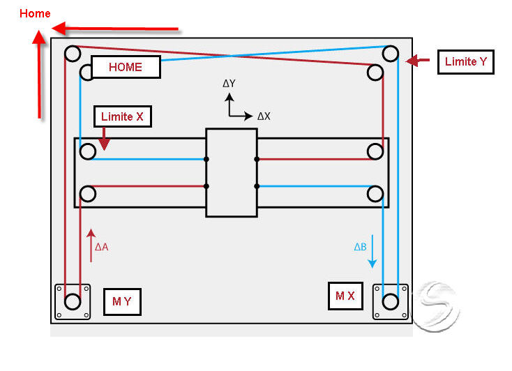
After many exchanges on the forum and many proposals and various tests, I take stock of my worries and various malfunctions Kinematics Core XY, MKS DLC32 V2.1 board, MKS TS24 rev 2.1 display, available dimensions 400X400mm, use of the latest version of LightBurn 1.7.08
I attach the plan of the kinematics, I would appreciate confirmation of the correct definition of the X and Y axes as well as those of the stops for the Y and Y homming
I don’t have a Z-axis, nor a probe.
I didn’t install any maximum stops on the X and Y axes.
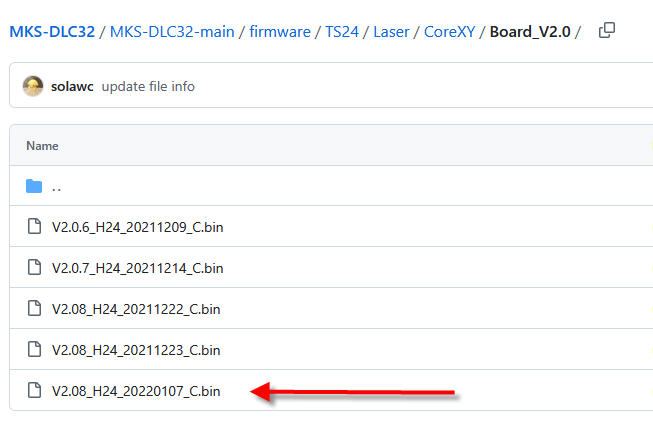
I also attach the type of FrimeWare injected into the DLC card and the file of my configuration under LightBurn.
The positive:
Homming works well with both LightBurn and the control panel of the MKS TS24 rev 2.1 display.
Dysfunctions:
The X- and Y-axis displacements are conformal from LightBurn.
On the other hand, from the MKS TS24 rev 2.1 screen, the X axis moves in the right direction and the travel distances are in accordance with my request.
On the other hand, the Y axis is the opposite of the movement made with LightBurn, but the travel distances are in accordance with my request.
In manual from LightBurn or from the MKS TS24 rev 2.1 screen if I exceed the maximum values, which I have configured (390mm) I can exceed this value, both for X and Y and crash into the mechanical ridges.
When I’m on home, manually from LightBurn or from the screen I can bring X and Y to negative values, so crash on the mechanical bumps.
For the record, I used this same cinematic with Marlin on a 3D printer without any particular problems.
Subsidiary question, with the MKS TS24 rev 2.1 screen is it possible to switch texts or icons to French.
LMG the Beginner !!
MKSConfig 18 04 25.nc (1,1 Ko)
This also currently happens with my MKS but as I use the display mainly for consultation, I don’t really care about it.
Depending on the firmware installed, it may or may not happen.
To resolve this you need to physically install the limit switches.
I believe that Lightburn does not work with negative values.
I know there are firmwares that allow you to change the language, but I have no idea about that specific one because I’ve never used it.
Allowing you to change the language almost certainly allows the French language, I just don’t know if the translation will be correct. ![]()
In the case of the Portuguese language, I chose to use English. ![]()
At this point you already have the machine working, right? Or did I get it wrong?
Hello Luis
Thank you for your detailed answers.
Yes the machine works, I just have to connect the laser and do the tests.
I made several attempts by replacing the laser with a small marker, it’s ok, the movements and dimensions are correct. I didn’t set up a hard engine the Z, what choice would you make with or sense of the Z engine.
What are the advantages of the motorized Z and in this case do you need a BLtouch style probe like on a 3D printer or is there another solution.
For switches with maximum limits, how do you connect them?
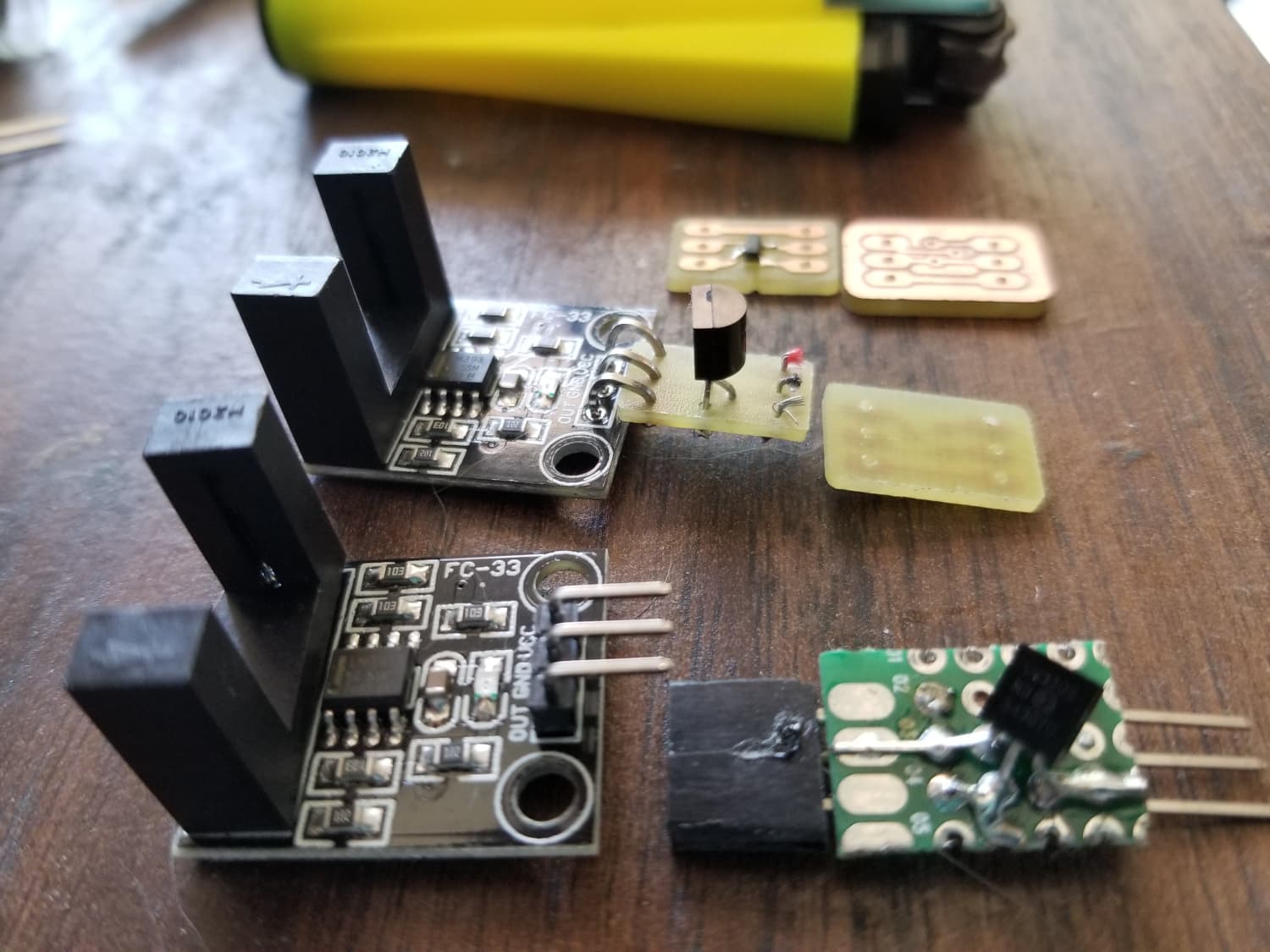
I have this type of model, Hall effect sensor with three wires (+ GND and E)

Lmgmo
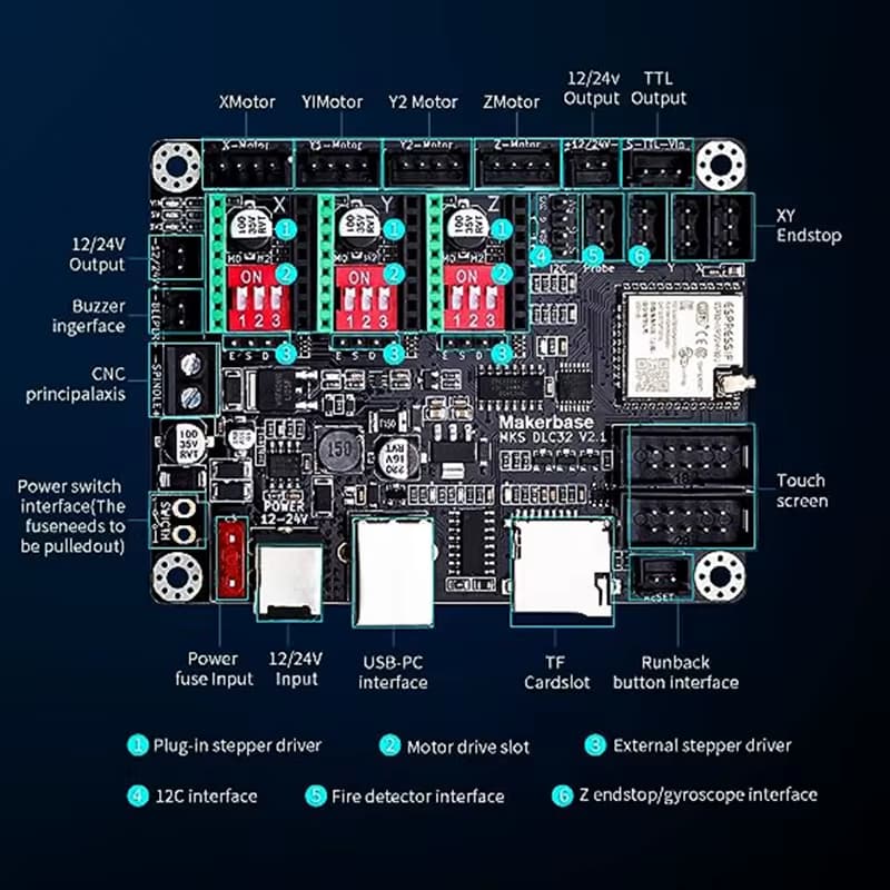
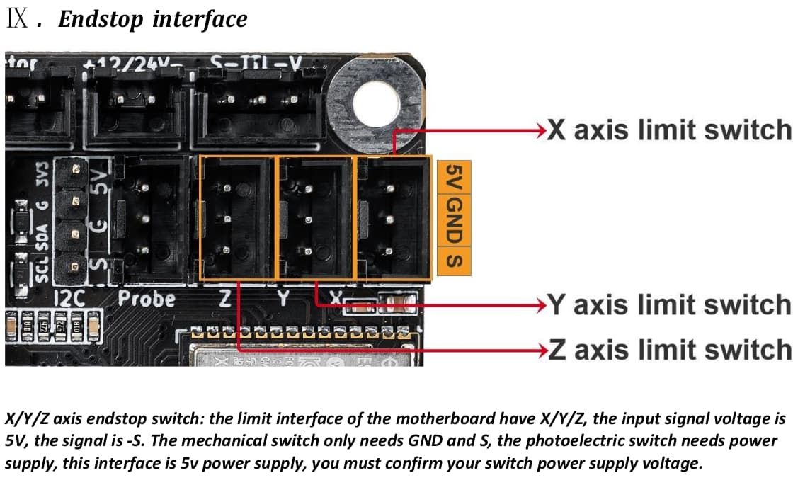
I am kind in a hurry, but I leave you an image of the MKS board where you identify the ports (connectors) for limit switches (up right). Of corse you have to eneble them by software later.
I am not familiar with thathose limit switches so I can’t guarantee at this moment if they are compatible or not.
I return later, sorry but I have to go. ![]()
These appear to be optical interrupters, not hall effect switches. These require some type of object to go between the two posts and block the IR from the sensor.
These all have wiring diagrams and most just pull a line low. If you want them pulled high, then you have to change the configuration.
![]()
Hello
Sorry,
I didn’t express myself well.
I have already connected the two stops X and Y to validate the homming in 0.0 and this on the dedicated connectors (endstop X and Y).
My question was: if I put two other stops for the MAXI limits of X and Y, how can I do it when there is no connector for it, maybe connect them in series, but how?
Stupid question, is it really useful to put bumpers on the maximum displacements?
Thank
LMG
It happens to me sometimes too. ![]()
From what I understand, the limit switches connected to the connectors mentioned in the image are “Hard limit switches” or “MAX” as you called them and are used for “homing”. The “Soft limit switches” are actually reference values that serve as a warning when working too close to the “Hard limit switches” but which are not actually physical switches. When I assembled mine I was thinking about the same problem and this was the conclusion I came to. I don’t think I’m wrong, but if someone more knowledgeable than me on the subject has something to correct or add, please do me a favor and explain the matter better than I can at this time.
If you use normally open (NO) switches, parallel them, if normally closed (NC), series them.
I don’t know what kind of output your interrupters are, but the ones I got went active high, I needed active low, so I added an inverter mosfet.
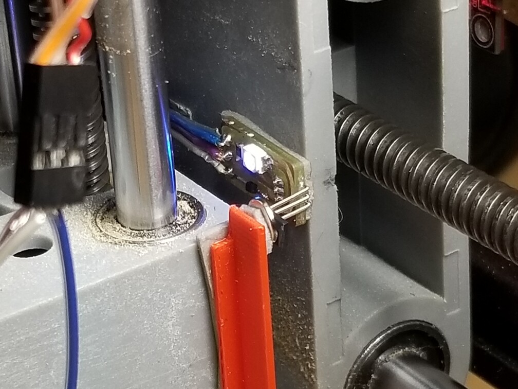
After a piece of debris was thrown into the interrupter, I went to a Hall effect type of detector.
If you’re going to use electronic type switches, then I’d suggest you use NO which have an open collector configuration allowing you to parallel their operation to pull a pin low. Many of these have both options available.
The software limits should keep the machine off these, if they do become active the machine has lost it’s location and will have to be re-homed.
![]()
1 Like
Well,
I see that the use of soft and hard end switches is not very simple. ![]()
On my side I’m going to stay as configured, since the homing works.
On the other hand, what bothers me is the control of the Y which is reversed on the MKS TS24 screen.
I’m going to do various configuration tests of the axes to see if I find the solution. I ordered an MKS TS35 screen, I’ll see if it works out.
Thank you for your feedback
LMG
OK, good idea indeed. I’m looking at
Thank you
LMG
As I mentioned before, I have the TS35 screen and the X axis is inverted on the screen compared to Lightburn, but that is not important to me.
Remember, you will need to install the appropriate firmware for the TS35 screen. ![]()
Parameter $21 is only if you have switches on both ends of each axis. It should be $21=0.
$20 is for using the controller software to limit travel along either axis. It uses the $130 and $131 parameters to establish how far you can go. Without limit switches, it should $20=1.
If you hit the frame using soft limits, reduce $130 and $131 a little bit until it stops without banging and gives you an error message somewhere.
A HARD limit will require a Home cycle to clear it.
A SOFT limit will stop and you can Jog off the limit. A Home cycle is not required.
This topic was automatically closed 30 days after the last reply. New replies are no longer allowed.