EzCad3 Experience: I’ve plenty of experience with this software (the good and the bad)
Lightburn Expererince: Nil (though happy to purchase a licence)
Model Development: I’ve plenty of experience in generating Bas Relief STL models for deep engraving. I use the laser like a 2.5D CNC (or negative 3D printer) to complement metal casting and final object creation across a range of alloys (Silver, Bronze, Copper, Zamak, Pewter etc - all of which I have depth profiles for accurate Z-Axis ablation control).
Time and Feedback: Happy to put in the time, effort and provide structured feedback (I’ve been an Alpha and Beta tester for others and ran a software development, support, and maintenance team).
Thanks
Nathan
PS - I’m not really into 2D marking but have done a fair bit.
My motivation, is that one day, I’d like to be able to put a piece of stock into the rotary, load up an STL model, and engrave a final piece (eg think laser “carving” a chess piece).
Hi Nathan, and welcome!
This is great timing, since we just put out a call to test the initial Ez3 support (linked by Jack)
Your work with metal casting is fascinating.
It’s great to have you on board!
Your goal to laser carve a chess piece on a rotary is ambitious, and I love it!
There are rumors that it will be possible to import STL files into LightBurn at some point.
For now, STL files can be converted to depth map images using online tools such as Sculptok to use 3D-Sliced.
Let us know if you have any questions or need help getting started.
Use our free trial, and make sure to import the laser’s config when adding the galvo.
I’m not sure I can contribute all that much till there is at least Z-Axis control to keep the beam in focus as it ablates down, and ideally STL support as depth map only give 256 layers??? Some of my engraves can have 1,000+ layers.
From my work with deep “milling” on the laser so far, you need to tune your profiles so each layer ablates the same amount as the Z-Axis moves (and this is different on every alloy). If you don’t get this right, your outside walls will no longer be vertical and will become increasingly concave as the laser drifts out of focus.
FWIW - my procedure for a new alloy, is to use a 5mm deep STL of a cylinder and I tune the prifle till the result produces a 5mm hole. I then know it is pretty accurate from then on for these sort of depths (but also found that it was still off on deeper 20mm work). As you can imagine this takes a fair bit of time. Once we have Z-Axis & STL support, I’d be happy to develop and share these profiles (as I did over on Laser Everything for EzCad3 - which I can do here if that helps at all).
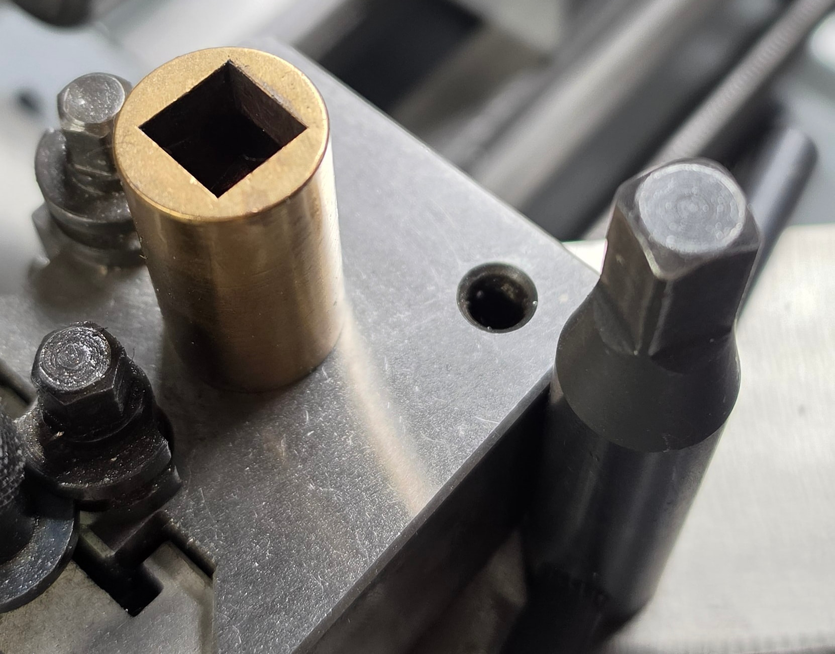
Here you go, one 10mm deep square hole “milled” into bronze for the retaining bolt for my lathe compound (one of the links above has the video on this).
To be fair, 1000+ passes is rare but even while 256 layers gives plenty of real world depth, it really requires Z-Axis control to be able to make something that is dimensional accurate or by the end of a attempted deep engrave the laser will be so out of focus you are more annealing the metal rather than engraving it: eg I use 0.01, 0.02, (and even 0.04mm) layers pending on the material, and the “detail” I want to get to minimise layer lines.
256 x .01 = 2.5mm
256 x .02 = 5mm
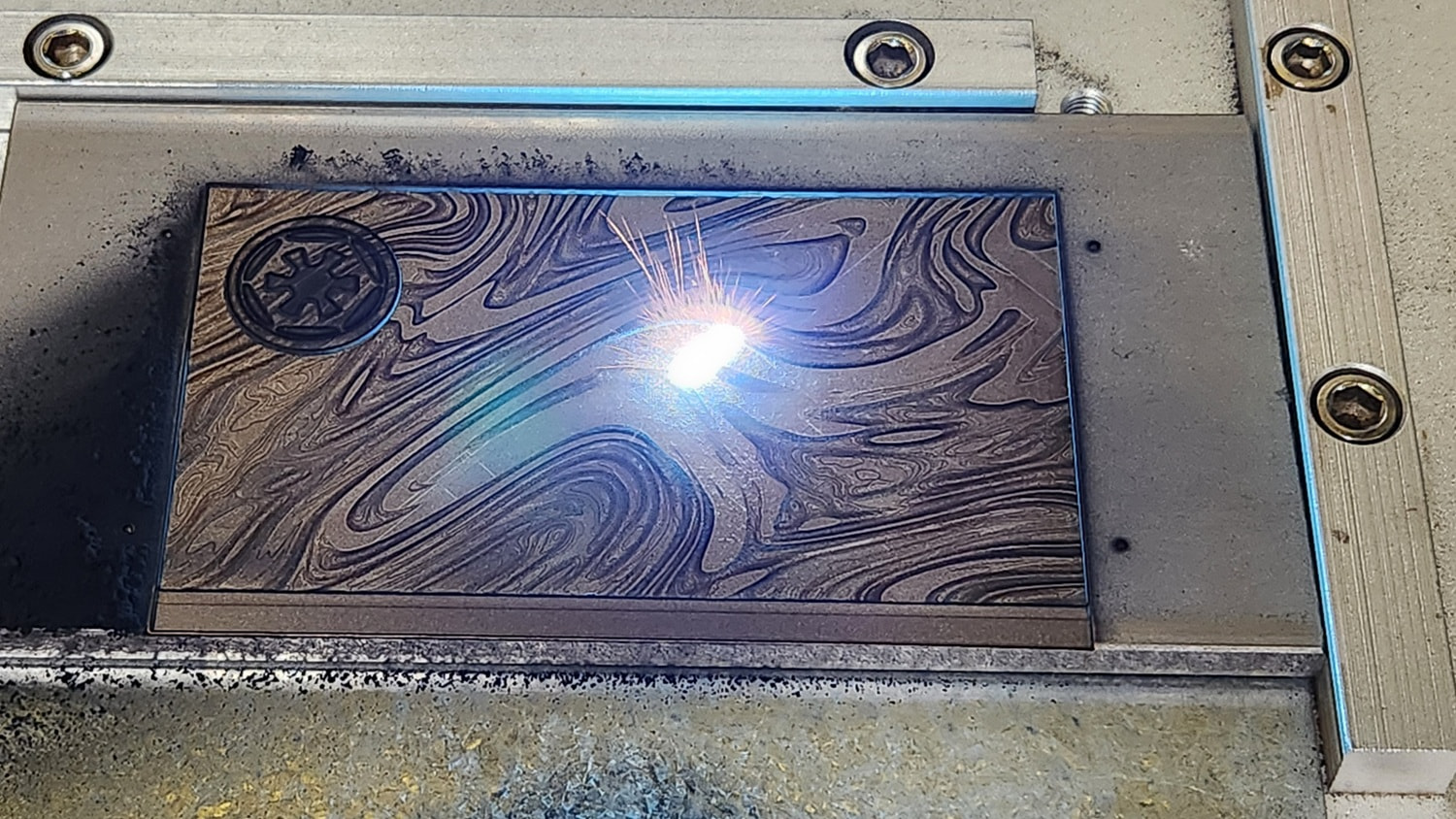
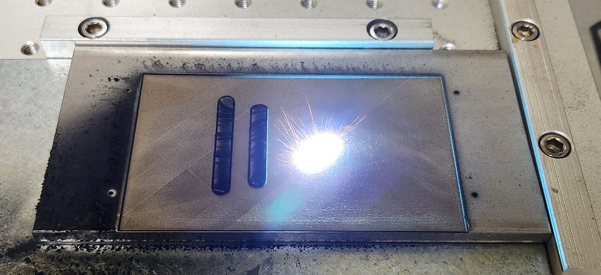
Here is another example where I was aske to make a two part mold in thick Stainless Steel flat bar. The engrave was over 3mm on each side and took over 30hrs for each side. While EzCad is clumsy and awkward, it does work for such work. Without Z-Control and supporting lots of layers by the time I’d dug down to the final few layers where the details are the edges would not be very perpendicular and the details would be lost.
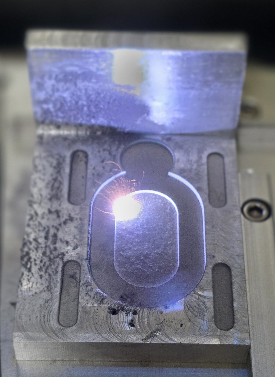
Its also great for all sort of layout and intricate milling, like this bracket. I designed it up as a 3D Model in Microsoft 3D Builder of all things, and used used the STL to mill it into the casting.
Note: These 2.5d lasers are not ideal for some of this work as you can not cut a vertical inside walls due to the beam angle, but if you just have outside walls and a good profile you are good to go.
Hi team, I’m testing the 2.1.00 RC-6 release with a JCZ DLC2 board originally from an SLM 3D printer.
The board is not detected by “Find My Laser” and hangs on “Waiting for Connection” when added manually as an EZCAD3 device on both macOS and Windows. I’ve confirmed the drivers are correct, but the Hardware ID is:
USB\VID_9588&PID_9979
It seems this SLM-specific PID might need to be whitelisted for the new EZCAD3 driver to initiate the handshake. Is it possible to have this ID added to the supported list? Thanks!