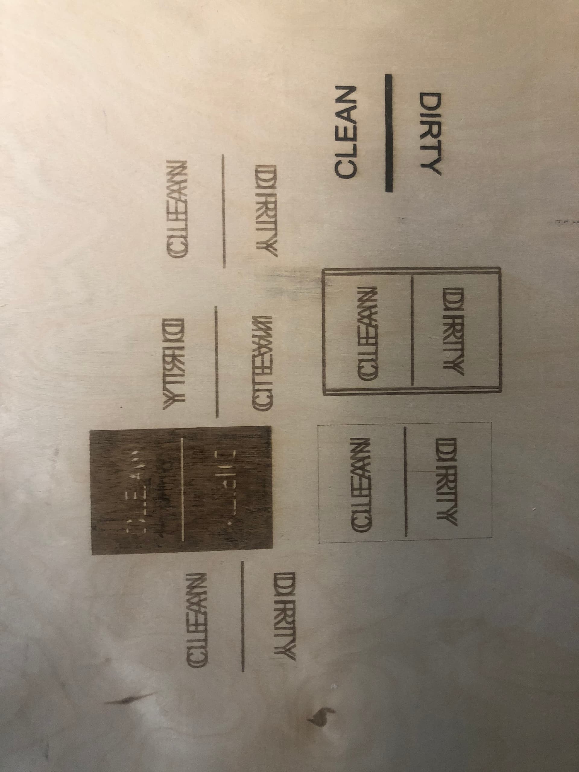
Good evening everyone. I am very new to the laser side of the house and am stumped on an issue I am having. For situational Awareness, I am running a JTech 24W Quad Pro mounted on a Mill Right XL CNC Machine. I have fixed the mirroring issue thanks to reading several posts here. BIG thanks!! However, I am unable to come close to this issue. So, everything I cut utilizing Lightburn seems to offset approximately 2mm. I was concerned that maybe the hardware was bad, so I cut the same gcode in VCarve Pro using UGS and it cut perfect. So now I am really baffled and would love some insight. The attached pic shows the trials with Lightburn and the one cut with VCarve. Again, any assistance would be outstanding and please let me know if you need more info.
Thanks again,
Mel
Can you provide the following:
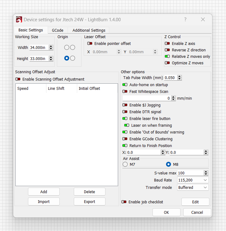
- screenshot of Edit->Device Settings
- upload .lbrn file that was used for this burn
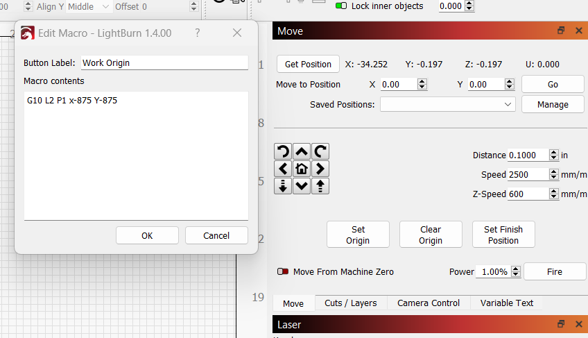
Also, not sure if it matters. The machine homes to the back left and and I had to write a macro to move the working origin to the front left. See pic.
From what I can see there’s nothing fundamentally wrong with the design. This leads me to believe one of following things may be happening:
- You have a good bit of backlash along the X-axis. This could explain the double image. One is created when burning left to right. The other is created when burning right to left. However, since you don’t have this with the VCarve Pro this is not likely to be the case unless VCarve is configured with some sort of backlash compensation
- You have an scanning offset issue. You can correct for this with a Scanning Offset Adjustment.
Scanning Offset Adjustment - LightBurn Software Documentation
However, this would imply that you have the same compensation on Vcarve. Can you confirm if that’s the case? - Your speed setting is extremely high. 200 mm/s is 12000 mm/minute. That’s likely faster than your machine is capable of moving. Whatever backlash or offset may be magnified at that speed. Also, are you comparing apples to apples with Vcarve in this regard? Were you also running at the same speed? If not, try matching speeds to see if that changes anything.
Overall, make sure you’re comparing apples to apples. Then eliminate any backlash if it exists. Failing that, set the scanning offset adjustment to correct for this.
Hey. Thanks for the assistance. I did as you recommended and slowed the LB file to match the VCarve file, which was 300ipm or 7620mm/m (see pic). Unfortunately, it did not change the outcome at all. Still double engraved. I’m not sure about the Scanning Offset Adjustment. I didn’t set up anything in VCarve for that and I don’t see any setting for that. Still lost in the corn flakes!!
Mel

Try a few tests:
- make a 10x10 mm rectangle. Set to fill and increase the line interval size in cut setting to 0.5 mm. Run the burn. Take a photo.
- make a 10x10 mm circle. Set to line. Take a photo. This will indicate if you have a backlash issue.
What speed would you recommend?
Stick to your current setting for the fill. On the line I’d suggest much slower. Perhaps 500 mm/min.
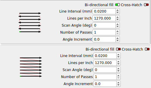
Can you control bi directional scanning (burning both directions of the fill)? Turning it off, so there it’s only a burning in a single direction?
This is Lightburn equivalent…
![]()
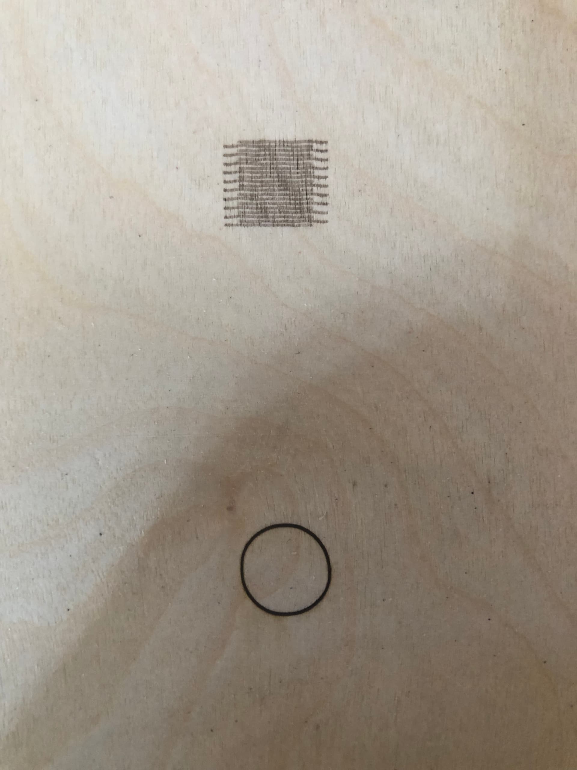
It looks like you don’t have a backlash issue but I’m noticing some other artifacts.
Note the waviness of the horizontal lines in the rectangle as well as the circle looking a bit oblong and irregular.
I don’t think that’s the root cause of the double image issue. That’s most likey from scanning offset. However, you may want to track down these mechanical issues once this is resolved.
In any case, I’d suggest working through the documenating on scanning offset adjustment to correct for the offset.
Scanning Offset Adjustment - LightBurn Software Documentation
You can continue to use the rectangle to measure and adjust settings.
I so appreciate your time and assistance. I know my feeds and speeds for the CNC, but this laser is definitely a different animal all together.
Mel
Hey there. Give a sec and I will give this a try.
The idea behind the single direction scan is to see if they then do line up…
Same game … although speeds generally refer to spindle rpm, it means power here… feeds are still the relative material movement.
The big difference is that you can compute the proper speeds/feeds for your CNC because the tool and the material are predictable…
With a laser, the tool and/or the material are known to be unpredictable and vary substantially.
Do yourself a favor and use that CNC knowledge to get the right speed/feeds for your laser… they are both machining operations, so the same game is afoot.
If it’s got a computer in it it’s probably a CNC machine, including my wifes’ Subaru… it’s fly by wire like most things today.
Like your CNC, it will cut at many different speeds/feeds but only within a limited speed/feed area does it operate the best with less tool wear and better material results. Your laser works the same.
You have a unique advantage most do not … use that advantage… It’s a CNC machine with a different tool, they are more similar than different … it’s all relative anyway ![]()
When you get a handle on this… you can pick up a fiber and not only can you vary the speeds/feeds, but also the frequency and q-pulse width… ![]()
Good luck
![]()
I don’t think there’s a question that it will line up. I guess the question for me is does the Vcarve do uni-directional scanning now? That would be relevant information for a comparison.
I agree, Vcarve must be correcting for it somehow, if that’s your point… seems clearly a mechanical issue.
Are these values not somewhere with the software…? Kind of like a scanning adjustment… I think you mentioned…
Didn’t mean to side track anything…
![]()
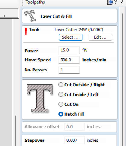
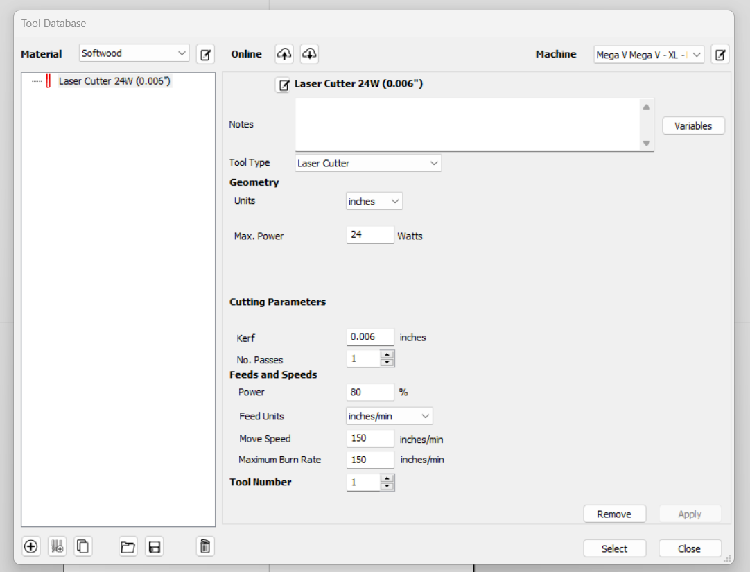
So, I was able to finally find that setting and cut it off. The square actually looks like a square and it fixed the ‘double vision’. I looked around in VCarve and couldn’t find anything remotely close. I attached a snip of the tool setup for the JTech in VCarve. But again, I just typed the letters and created the gcode for UGS. However, the circle is still a little squirrely looking.
Mel
Does Vcarve burn in both directions or no?
If not, you may be masking the issue by going in one direction.
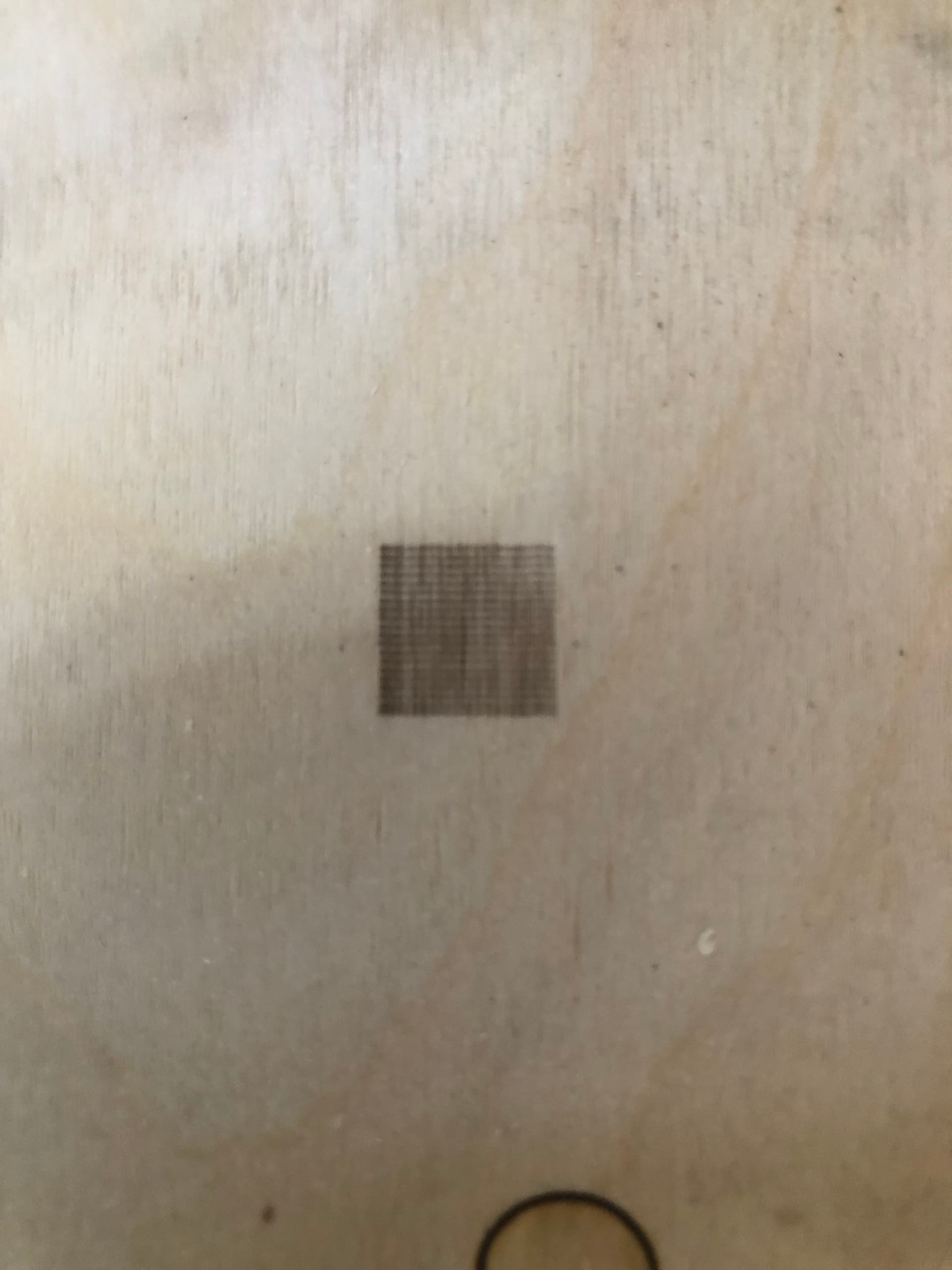
Try this:
- create a rectangle
- in Cut settings create one sublayer for fill and one for line; turn off bidirectional fill as you did in the last photo
- run the job
I’m curious to see if the outline will go around the filled portion.
This was more to confirm that’s the issue…
![]()