Drop Z axis adjustment

Hey Everyone, I recently purchase a Gweike Cloud 50w machine. With their software we had to click on the z- button for the drop z axis adjustment to get a clean cut.

On lightburn I’ve ran the auto focus but am not sure where to change the z-settings. All my cuts are coming out very wide and are not cutting through my mdf. On the auto focus chart they are coming out at 0.0 where as the clean cut I need would be a 10.0

Dear Ken,
I had the same issue on my Gweike Cloud machine. I found that setting while watching the “Gweike Cloud and Lightburn” YouTube video.

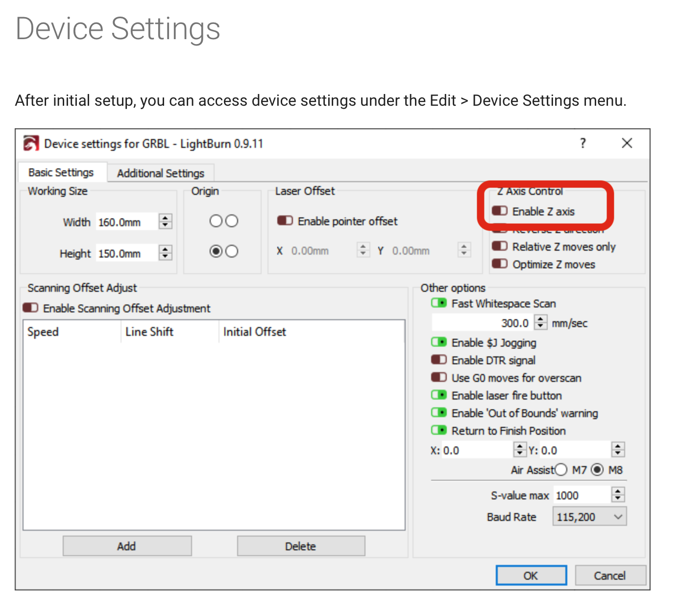
Go to Machine Settings and enable z-axis:

After that you will see a new field “material thickness” in your "cuts / layers - window"
material thickness

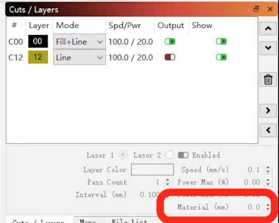
Here you will have to enter “material thickness + 11mm”. For example I often use 3mm basswood, then the setting is 14mm.
I was not able to find out where to enter the constant of 11mm yet to enter the real material thickness there…

Give it a try!
Regards from Austria, Tom

ATTENTION
I do think my answer works for 3mm material only. Today I wanted to engrave some slate with a thickness of 8mm. So I added 11 and set the value to 19mm. >> crashed into the material.
I think the formula must be 17mm MINUS material thickness. That takes me to a setting of 17-8=9mm for 8mm thick slate. Then it engraved fine…
Does somebody else agree with that??

Regards, Tom

1 Like

This topic was automatically closed 30 days after the last reply. New replies are no longer allowed.

I think I worked this out so that it moves down at the start of the cut, and moves straight up to the home position at the end. I haven’t had a crash yet doing this. (I’m still new to my Gweike cloud, so I’ll update this if I get more info).

To set up my Gweike Cloud Pro with LightBurn, I:

  1. Plug in usb cable from laser controller to computer. (note: there are two ports, one for the camera and one for the laser controller)
  2. Install drivers from Gweike website as per this video: How to use Lightburn with Gweike cloud - YouTube
  3. Open LightBurn
  4. Laser window>Devices>Find my Laser (Ruida 644xg, rear right)
  5. Laser window> select correct comm port and Gweike Cloud/Ruida machine you just set up
  6. Edit menu>Device Settings> Enable Z = on, Optimize Z Moves = on
  7. Cuts/ Layers window> set Material (mm) to 17-thickness of your material (e.g for 3mm ply, you would calculate 17-3=14, therefore put 14 into the Material(mm) field.
  8. Enter material settings: GweikeCloud Parameters Setting Table
  9. Design/frame/cut your thing.

==== Notes ====

Saving to the library

When saving to the Materials Library for the Gweike Cloud Material Library - LightBurn Software Documentation you need to enter the Material (mm) value (e.g. 14 for 3mm ply) into the “Thickness” field to preserve it with the settings. You may wish to note the real-life material thickness in the field of the Material name or Description, for ease of recognition:

Z Offset / Z steps per pass
If you want to use these settings (e.g., to defocus a bit just while doing raster engraves in a job where you have cuts and engraves (offset), or to move down into the material with each pass in a thick material so that the cut is better in focus (steps per pass), they can be accessed via the cut settings editor (double click on the layer). The main thing to note for the Gweike Cloud is that THE DIRECTIONS ARE REVERSED. Do NOT go by the in/out indicator in the dialogue.

A negative value will take the laser head closer to the material and a positive one will take it further from the material. If it helps to remember, imagine the Z axis is a traditional vertical one; up is positive and down is negative; a positive value in Z offset or Z steps per pass will take the laser head up, a negative will take it down.

These settings are compounded upon the Material (mm) setting. So set your material correctly first (as above) e.g 3mm ply is 14, then add the amount you want the laser head to move up or down from that height in the Z offset/ Z steps. e.g if you want to defocus a little for an engrave you would put 1mm in the Z offset field (NOT 17-4=13).

Camera Setup
There are two stages to camera set up, Calibrating the Camera Lens, and doing the Camera Alignment.

Calibrating the Camera Lens

  1. Plug the camera usb port into your PC and turn on the laser.
  2. Print the calibration dots at 50% scale and adhere it to something flat (e.g corrugated card) so the pattern isn’t distorted as you will need to prop it up on angles due to the fisheye lens.
  3. Laser Tools> Lens Calibration Wizard > Choose SHUNCCM, Fisheye Lens, no preset
  4. The Cloud Camera is a fish eye, so after the first (flat/centre) capture, you will need to tilt the dot pattern toward the camera to get it to capture correctly (not lay it flat). The camera and dots need to be still when you capture them so prop the card up in the machine against another small object (e.g. a tall stack of post-in notes), to tilt the outer edges toward the camera, and I used the front access panel (the door where you slide the honeycomb in and out) to move the dots around to keep the camera super still. The stock lighting inside the machine is uneven so I also set up two overhead lamps to add some more. I had the best captures when I ensured the dot pattern was upright in the camera view (the ‘top’ of the longer sides has fewer dots than the bottom).

Camera Alignment

  1. The Material Thickness in this menu does NOT move the Z axis, it’s used on the back end for calibration. So before opening this menu you will need to get the machine to move the Z axis to the correct focal height for the material you are engraving. Use the Move window to do this by changing the distance to the focal length of your material (given by the equation 17-thickness) e.g. if your material is 3mm thick, enter 14mm into the distance and hit the Z down arrow (bottom left of the directional keys) to move the head down.
  2. Laser Tools > Calibrate Camera Alignment > Fixed position > SHUNCCM (check you can see the camera feed) and click next.
  3. Change the material thickness here to the ACTUAL thickness of your material (e.g 3mm for 3mm thick ply)
  4. Complete the alignment as per the guide.
2 Likes