Hi.
I want to thank other users on this forum for their invaluable help and advice to enable me to create this.
I hope others can use this to get the best of their laser cutting world.
For a while now I have had a a 130w 1390 CO2 Laser. I have been very happy with its cutting ability, however for fine laser engraving it does not work so well. Call it “Walnut with a Sledge Hammer” syndrome.
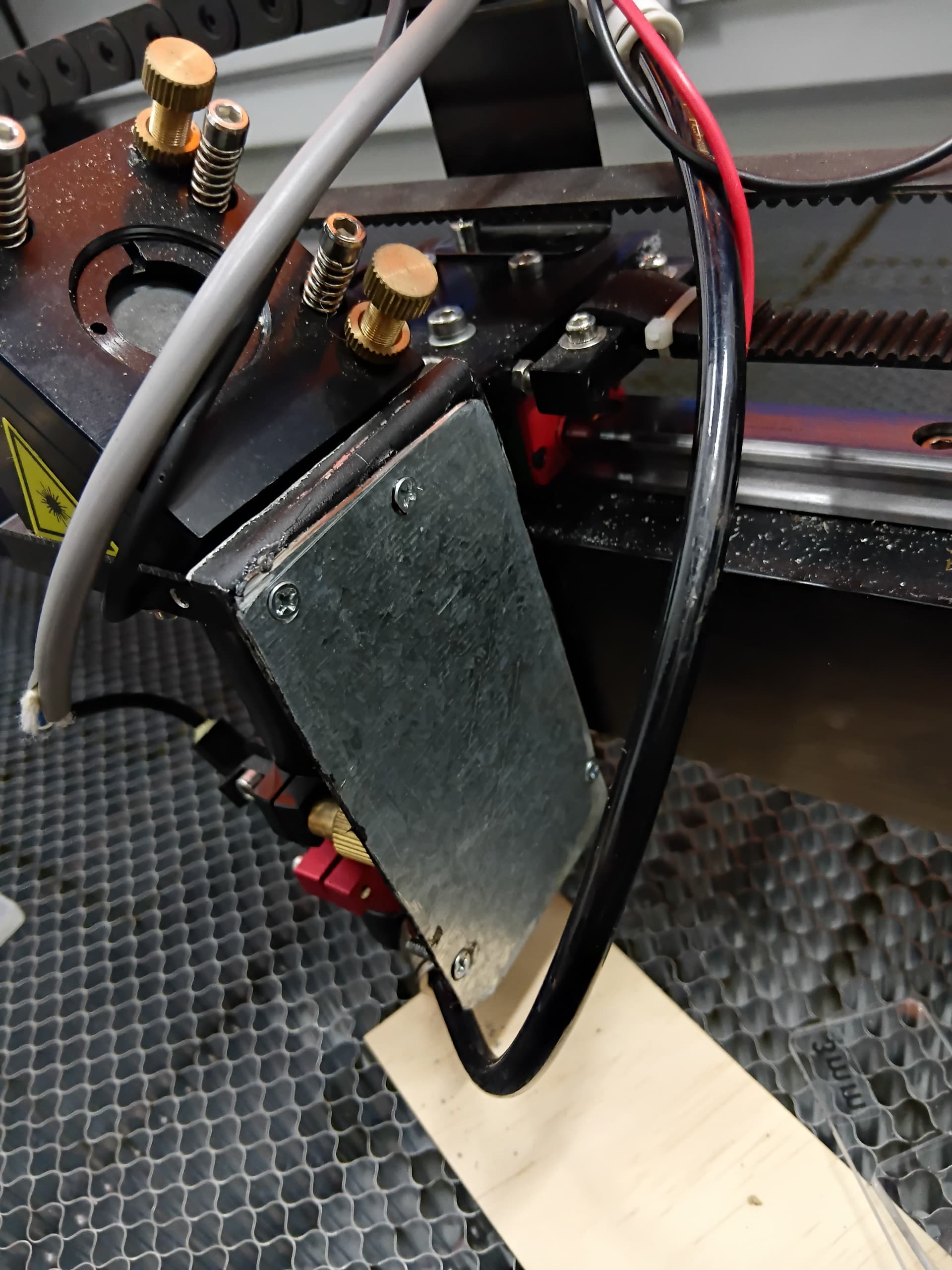
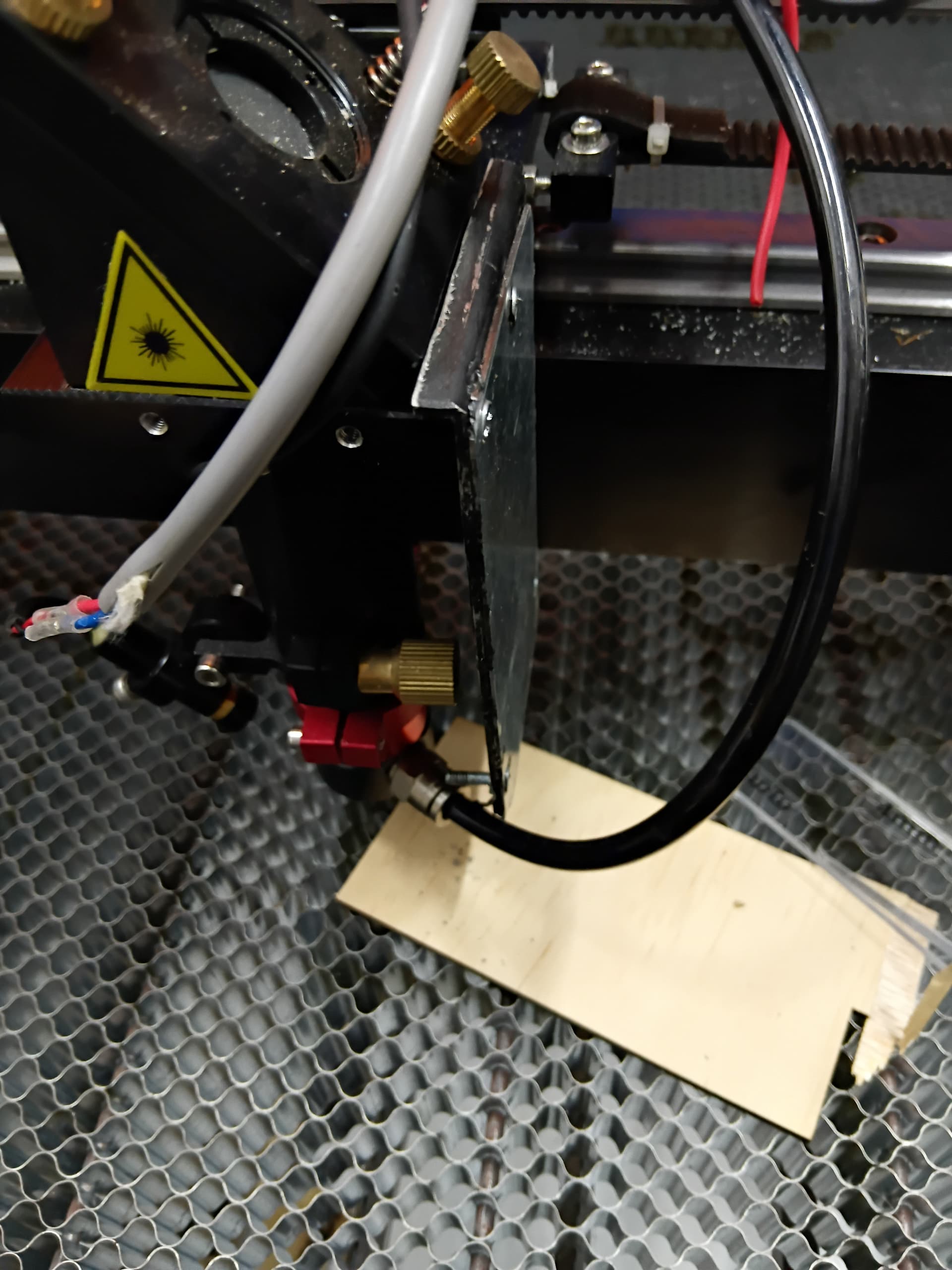
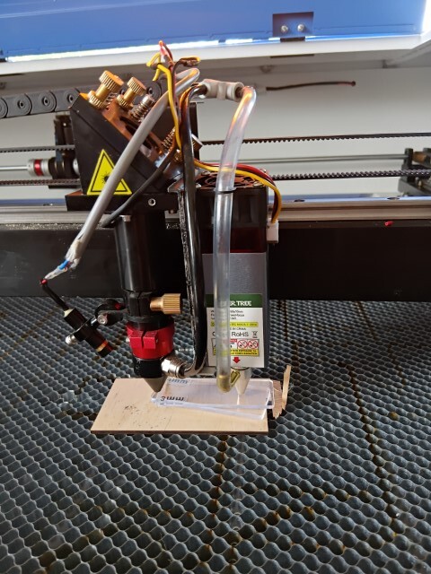
Looking at the mounting for the focus lens I noticed that there was a place I could mount the LED laser.
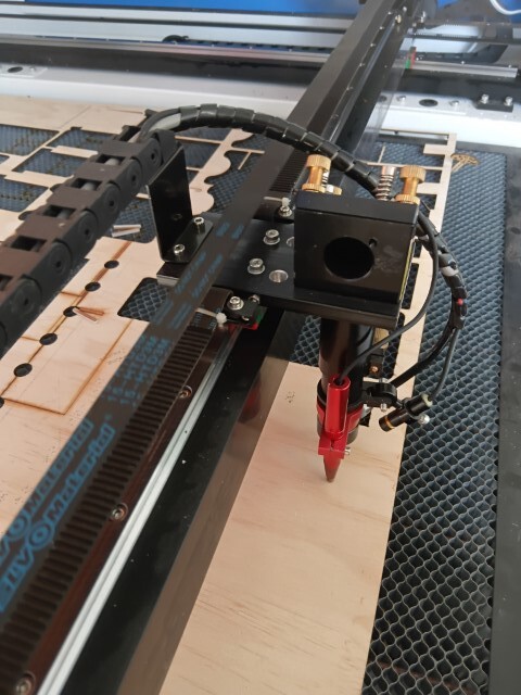
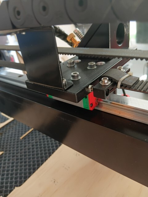
As there was plenty of clearance it seems the best place to mount it.
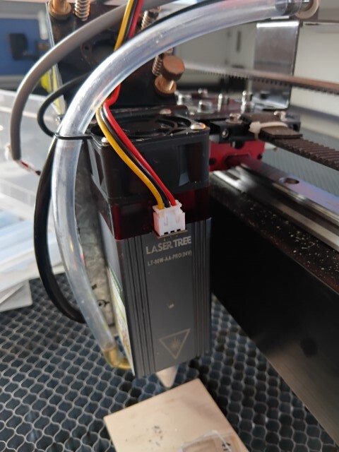
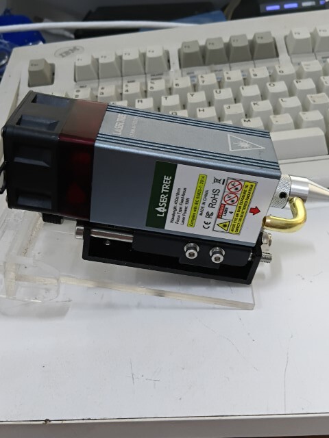
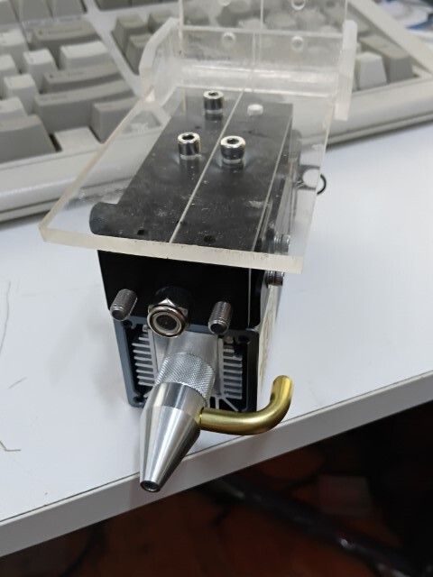
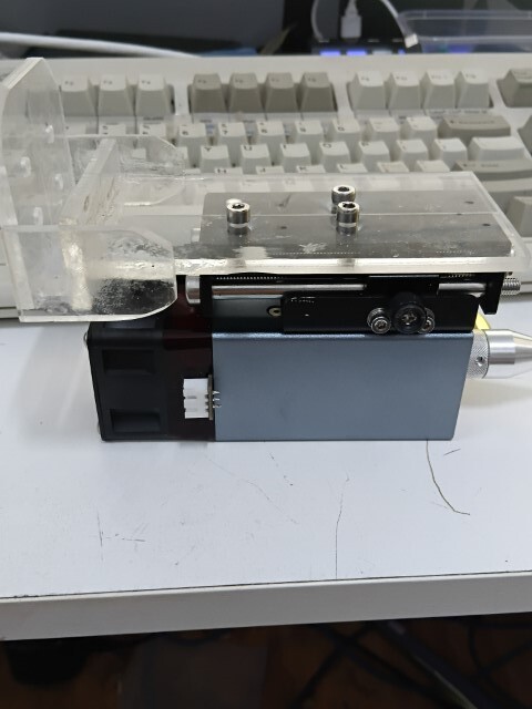
So I purchased a Lasertree LT-80W-AA Pro.. which has 2 x 5w blue lasers, and a adjustable slide to mount the laser on. Then using 4mm acrylic I bade a mount for the laser.
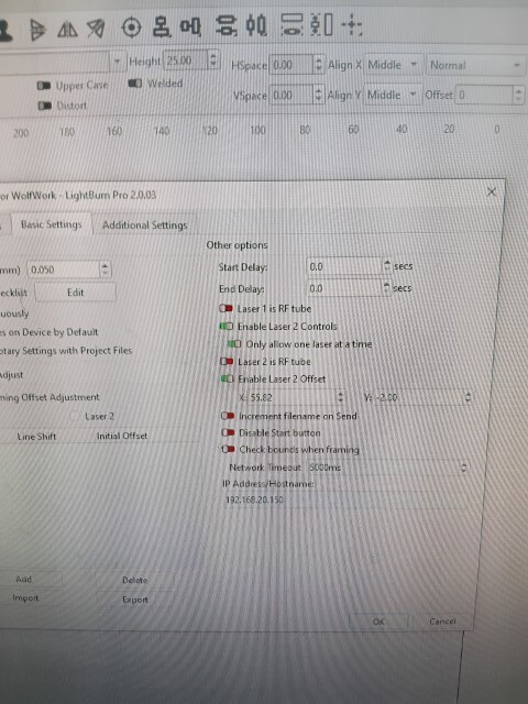
Ok.. That was the hardware mostly done. But I needed to control the Lasers. The Ruida does handle 2 lasers however it is fifficult to split the type of lasers between them.
Leaving the Ruida as Active_LOW and Analogue voltage seems the best way to do it. With measuring I found the Ruida would put out from almost millivolts to the full 5V.. with my CO2 Laser firing for the full range.
But the Laser Diode requires PWM. and has no safety override.
I did find some 555 based Voltage to PWM.. (Pictured Here)
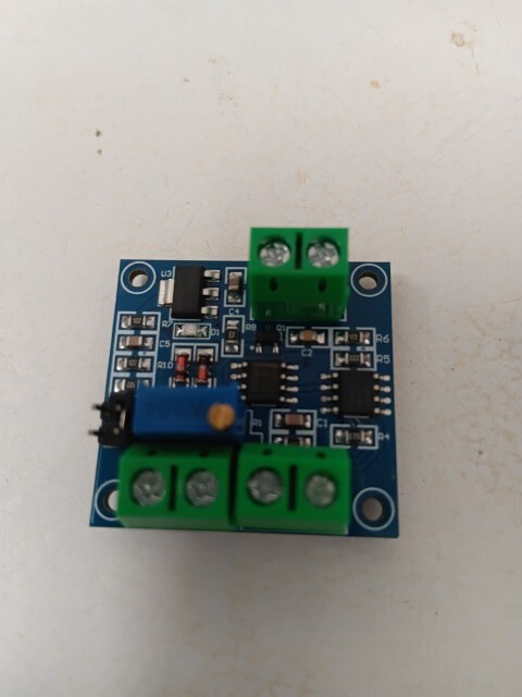
But I found it would not produce PWM till at least 1.5v.. And I needed a higher range than that.
But I could use a microcontroller to do this for me.
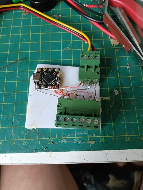
Using a DF-Beetle (Arduino Leonardo) controller I could program it to handle the safety AND the V to PWM convertor.
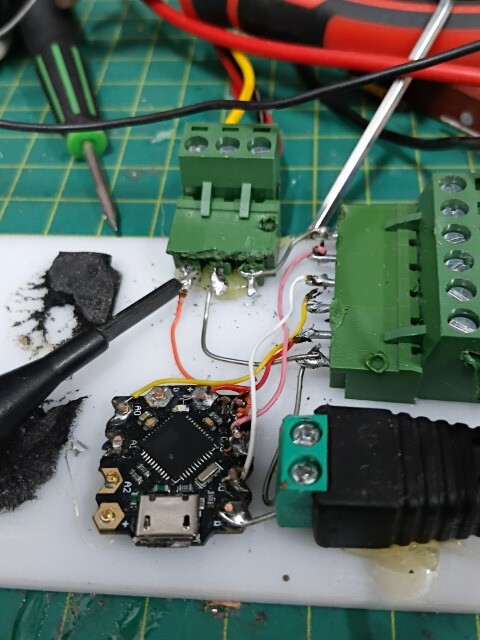
Here is the Code I wrote.
//Author David Boccabella
//Translating the Ruida Analogue Output
#include <TimerOne.h>
unsigned long _Freq = 5000; // default 1000 μs (1000 Hz)
unsigned long _DutyCycl = 500; // default duty cycle 50%
unsigned long _FocusVal = 5; // default Focus Value// Pin Designations
const int _LaserVol = 0; // Analogue Voltage In
const int _PWMOut = 9; // PWM Out to Laser
const int _FocusMode = 10; // Laser on at FocusVal
const int _LaserON = 11; // Failsafe from Rudiavoid setup() {
// Set up the Pins and default Level states.
pinMode(_PWMOut, OUTPUT); //PWM Output 0-1023
pinMode(_LaserON, INPUT_PULLUP); // Fire Laser on LOW
pinMode(_FocusMode, INPUT_PULLUP); // Low power Focus Mode// Initialise the Timers..
Timer1.initialize(_Freq);
Timer1.pwm(_PWMOut, _DutyCycl);
}void loop() {
_DutyCycl=0;
if (digitalRead(_FocusMode) == LOW) // FOCUS
{_DutyCycl=_FocusVal;}
else
{
if (digitalRead(_LaserON) == HIGH)
{ _DutyCycl=0;} // Set PWM to 0
else
{
_DutyCycl = analogRead(_LaserVol); // Get voltage from Ruida
}
}Timer1.pwm(_PWMOut, _DutyCycl); // set the change
}
Using the TimerOne.h library it gave me a full 1023 PWM control, rather than the 255 interger one.
It even give me a way to have the laser on very low for focussing by pulling Pin10 LOW.
Pin 11 and A0 accepts the Ruida output, and pin 9 goes to the laser as the PWM out.
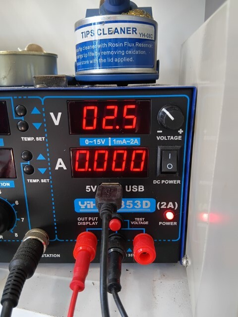
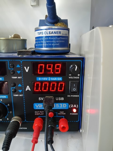
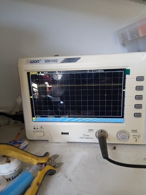
Here are some tests showing the Voltage in.. and the PWM.
2.5V
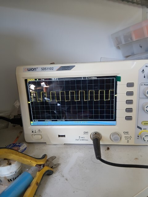
4.9V
Thats all for now. I will cover the installation and setting up in a few days
Enjoy.
Dave