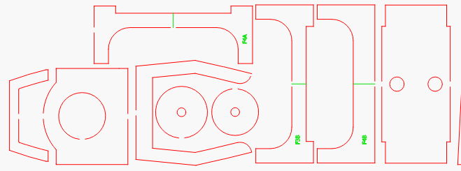
Bernd is asking if those are tabs in the original, as in intentional gaps so the pieces don’t fall out of the wood. If you can post the original file (either here, or email to support@lightburnsoftware) I can have a look.
The auto-join tool uses really close tolerances at the moment. The ‘Close shapes with tolerance’ would let you do anything with only a single gap, but anything with two breaks in it would be considered two independent shapes, so they won’t ‘close’ - they would have to be joined with each other.
I can close these gaps using the ‘Draw Lines’ tool to snap the start of the new line at one end of the gap and dragging until the line snaps to the other end of the gap. Do this again for several of the gaps, then select all that you have edited, both the new line segments and the original sections you are closing and use ALT-J to join these sections.
Selecting ALT-J will try to auto-join these sections into a single, closed path shape. You can see this change indicated by a direction change in the “marching ants” marquee of the selection. You can find open shapes by selecting ‘Edit’→’Select open shapes’ from the menu.
Why won’t it work here? You will need to edit the line if what you want is for the segment to follow in the same arching path, but it does work.
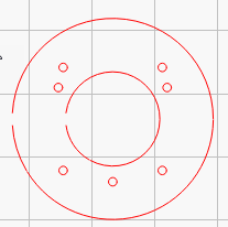
I don’t find the exact same section in the file I have but it does have circles with gaps, so I will use that in my example.
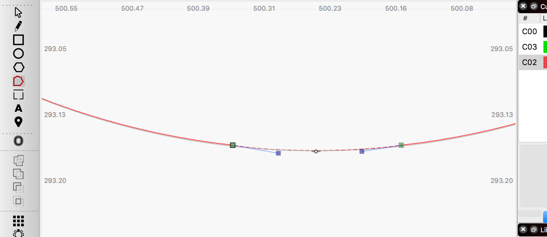
I draw a line segment snaping to the ends of the gap, then enter the ‘Node Edit’ mode.
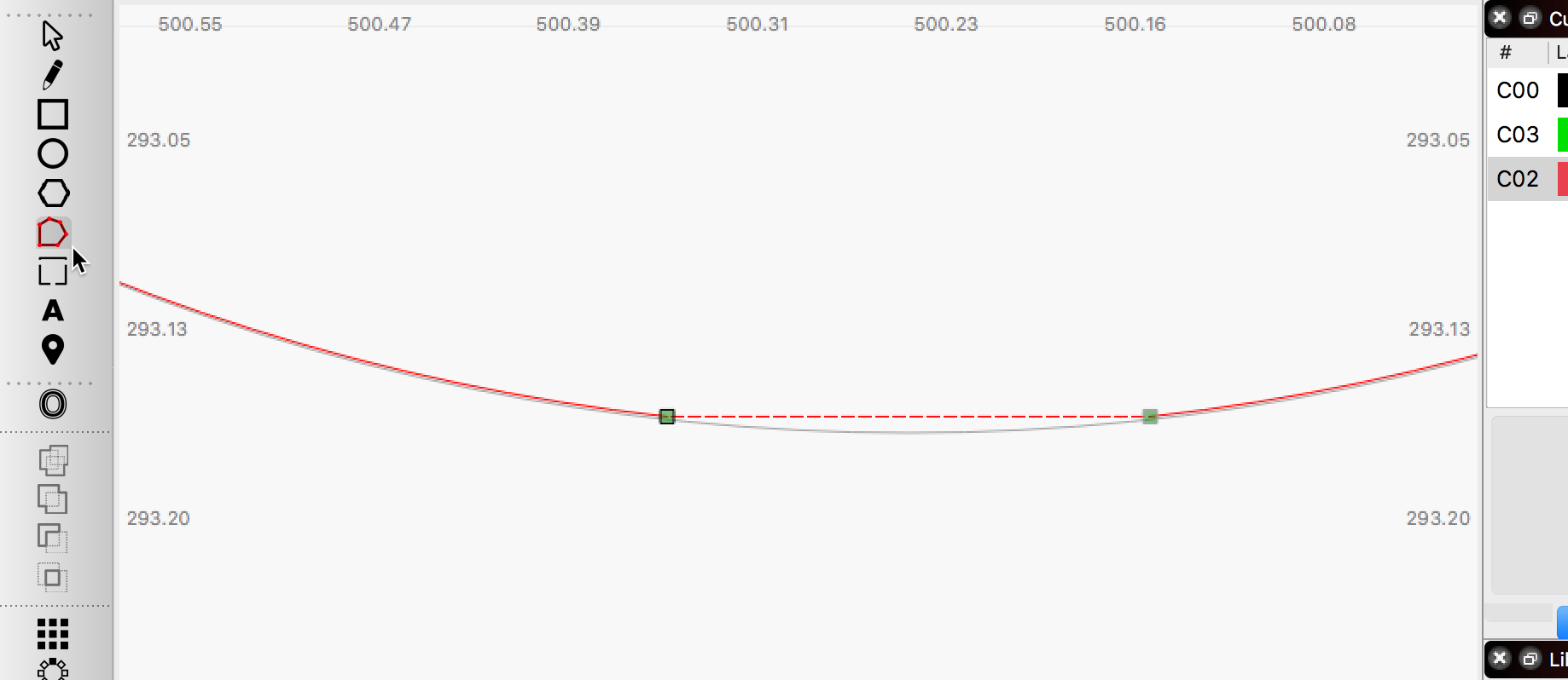
Grab the center of this new line segment and drag down to match the arching shape. I drew another circle and used it as a template to help with visual alignment.
Again, selecting ALT-J will try to auto-join these sections into a single, closed path shape.
Yeah I forgot about “Node Edit”, that worked. However, I still see no results with ALT-J. I it supposed to take the original circle and join it with the new segment?
If so it doesn’t do that. So how does one end up with a complete closed circle after the “node edit”.?
I do not understand why this is not working for you. These are the exact steps I took and it works as expected here. Make sure you have both the original semicircle and the connecting line selected and choose the menu item ‘Edit’→’Auto-Join selected shapes’. Are you saying that when you do this, the 2 shapes remain as independent shapes and are not joined into a single object? Are you using the hot-key or doing this task via the menu interface?
Try this, pull the line node away, and without letting go, snap it back to see if it closes.
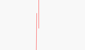
I must not be doing it right. The circle has a break in it. I draw straight line from one point of break to the other. I adjust it with node edit. I then select the circle and the line and ALT-J. The line patch stays as an independent part.
How far off is it? Given that the sources were offset, they weren’t “the proper arc” to begin with, so unless you’re cutting engine parts with your laser, I doubt that level of accuracy is required.