Edge Valleys and TCON/TCOFF for Galvos

Hi Everyone –

We are also using a 30W galvo for precision laser engraving for an industrial application. In our application, we are seeking to achieve a precise and uniform depth of engraving with good surface finish.

In prior tests, we found a deep valley outlining the perimeter of our engraved shapes. We measured the valleys to be 10-15 micrometers deep, and the depth was proportional to the number of passes. See picture below showing the edge valley at around 12.6 micrometers deep.

We surmised the cause was due to the galvo slowing, stopping, and changing directions near the edges at constant power. This led me to investigate setting the TCON and TCOFF settings, and I used the test designed by dannym to set these values. We ran these tests on stainless.

TCON and TCOFF were previously set at -300us and 100us respectively.

Here is test with our original settings:

Here is the test with our updated settings after running the TCON/TCOFF test:

In terms of the result, this appears to have significantly reduced or eliminated the border valley.

Overall this test appears to have significantly improved our edges and eliminated the valley. We will perform more inspections and tests in the coming days.

Our final settings are: TCON: 157us, TCOFF 235us, EndTC 300us (unchanged), Polygon TC 100us (unchanged), Jump Speed 5000 mm/s, Min Jump Delay / Max Jump Delay: 0 us, jump distance limit: 10 mm.

1 Like

Here is a microscope picture with original settings showing the edge valley:

Here is a equivalent picture with updated settings. We cannot see the edge valley here:

1 Like

SWEET!

I sat down with this problem for quite awhile before coming up with this calibration pattern. Went through a lot of iterative ideas before I got to this, which is both accurate and straightforward to interpret.

I think the pattern itself is basically perfect. I came up with it in the middle of this thread, you can download it here and read the discussion:

I think there’s still a problem though, limiting calibration in some cases.

I discovered the galvo starts vector lines from a standstill. What it needs to be doing is like what a CO2 laser with Ruida controller will do- it always runs rasters at constant velocity, by padding it with braking/accel buffer space (“Extend Space”) outside the raster content, what we’d call “overscan”. The Ruida calculates how much space it needs to add based on the max acceleration limit programmed onto the controller, along with the velocity the job will raster at. Actually overscan is not an LB feature at all, not on the Ruida anyhow.

It turns out LB doesn’t do “overscan” with the BJCCZ galvo controller (yet), the mfg doesn’t offer any open data on its interface. LB reverse-engineered it and got it running, but if the BJJCZ can do overscan, LB can’t command it to do that yet. I thought by including vertical bars on the left and right it would accel there, then skip over the white space at the commanded speed and then fire on the black space with it already at constant speed.

It doesn’t. It always starts each feature from a standstill. The black space after a white space is a a feature. It starts from a standstill, turns on the beam, and accelerates down the line. So beam energy can fire more that asked for in the first 0.5mm or whatever when you max out the speed.

The DELAY settings don’t actually fix the prob. That would still start the galvo mirrors moving from a standstill, travel down the line, and wait DELAY before starting the beam. But that would only make a blank section, which is worse. The only thing that can fix this would be overscanning, or sticking with lower speeds that don’t have as long of an accel zone.

At the endpoint of a vector, it doesn’t have this problem. Just flies past the endpoint and turns off the beam as it passes.

I saw it on some tests with highest speeds and the pulse freq turned down until it’s making a pulse at a spacing of about 1.5x the laser spot size (40um for an F100 lens). The pulse is so quick on a MOPA that the pulse is still basically a dot, no elongation, even at the highest speeds. So at 6000mm/s, a freq of 150KHz would make circular 40um dia dots every 40um. So circles with the edges barely touching. At 100KHz, there’s a 20 um gap between dots. But they’re not evenly spaced at the start point, they may overlap several pulses before spreading that far out due to the speed. The BJJCZ probably doesn’t have a feature that allows it to proportionately reduce the freq when the actual speed has not yet reached the commanded speed.

If you set the pulse rate high enough that pulses overlap normally, an add delay, that could actually mitigate the problem. Like at 450KHz, every dot would have 1/2 the dot before it overlap (circumference of the circle before it reaches the center of the dots before and after) and 1/2 the dot after. Say during accel it fires 6 overlapping dots, cutting too deeply. If we delay by 2.2 us, it skips the first 3 dots, and the actual gap from the correct start point to first pulse could be insiginificant.

However, I have a 300W MOPA. So far, the “golden rule” I came up with has always been true- don’t overlap pulses, either along a raster line or the stepover between lines. Overlaps rapidly overheated the surface, it seems to melt the surface and the laser can’t make little particles explode off the surface where the beam hits a liquid spot. It just makes it hotter.

I may be a corner case there because very few people have 300W. I’m overpowering it. I could reduce the power to 10% and should see what you see on the 30W in theory. But that would throw away the advantage of the 300W source. I’d rather keep the power up and increase the speed to spread the pulses out to avoid overlap. But now I’m asking for such high speeds that the accel length causes this prob

As a simple test, if you disabled bidirectional engraving, overrode all the timings for your layer, and put a small thin rectangle off either side of your engraving test area, you could simulate that overscan - like this:

If you set all the timing corrections to zero, and used uni-directional engraving, the middle rectangle should be a “pure” test area with no start/stop pauses.

I have actually been meaning to try this myself - IE, LightBurn can add overscan moves for diodes, and do the extension based on speed. We could also do the scanning offsets like we do for DSPs to correct for timing differences on left->right vs right → left passes, but that’ll require some playing with to get it right. I think people are so used to TC’s for galvos so for now what we have is sufficient, but I believe there’s room for improvement too.

1 Like

But that’s what I tried to set up in the tcon_tcoff_test_v04.lbrn2 test.

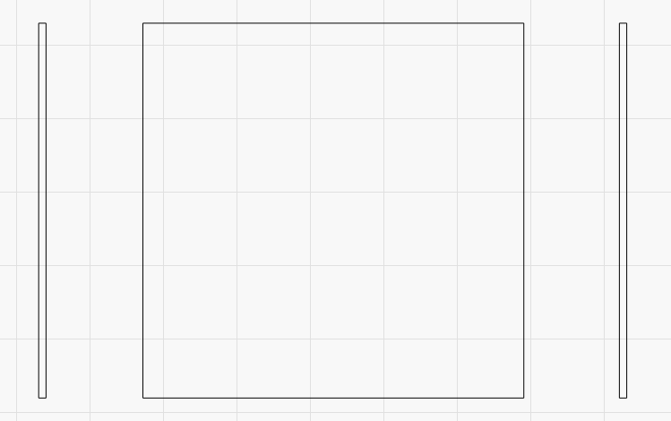
There’s some narrow bars on the left and right, intended to do exactly that. Turn off bidir, the skinny left and right bars are not read for cal, but to make a pseudo-overscan scenario. They appear as blue on my screen but are actually a blue bar superimposed over a red so they apply to both directions.

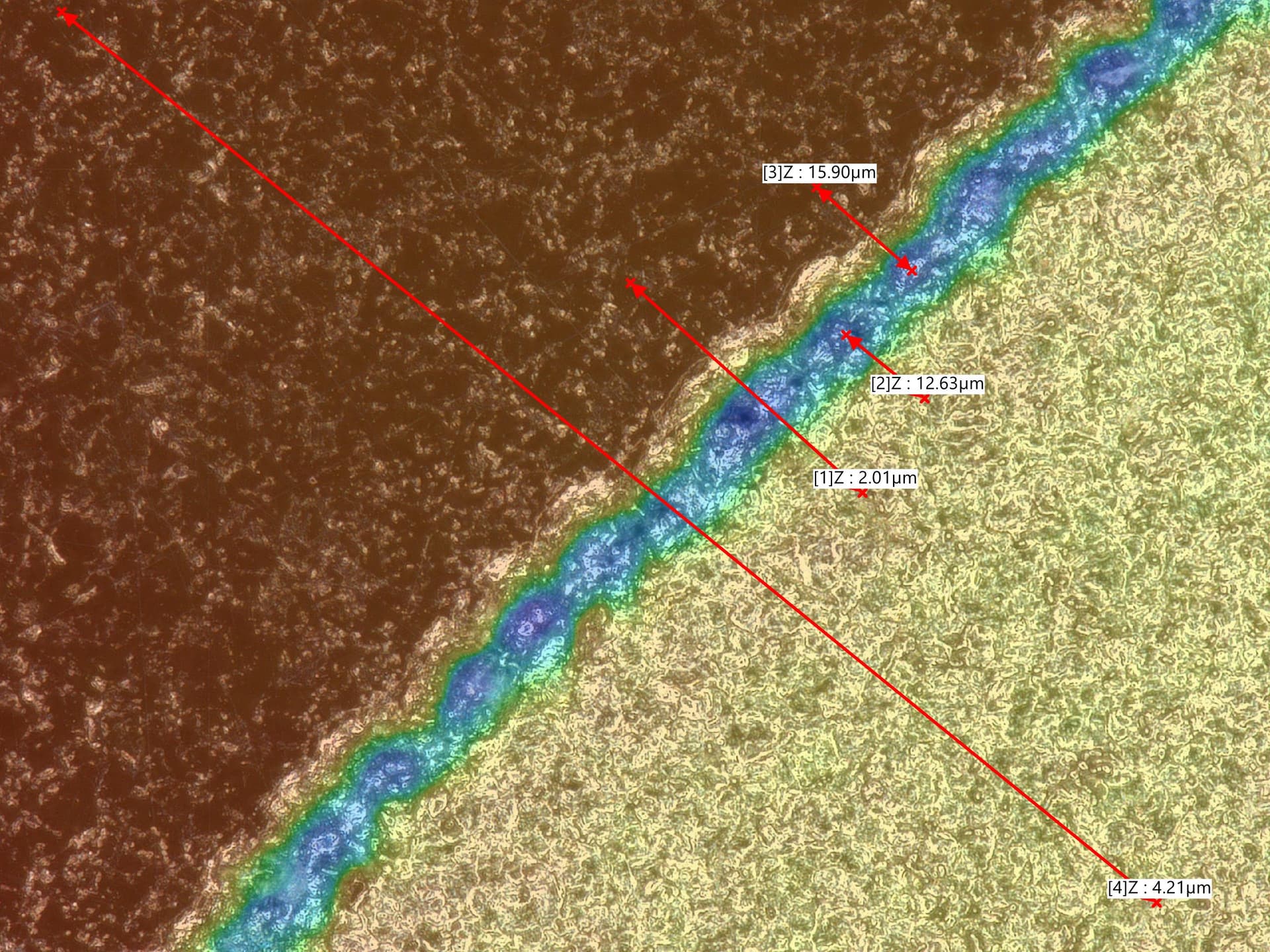
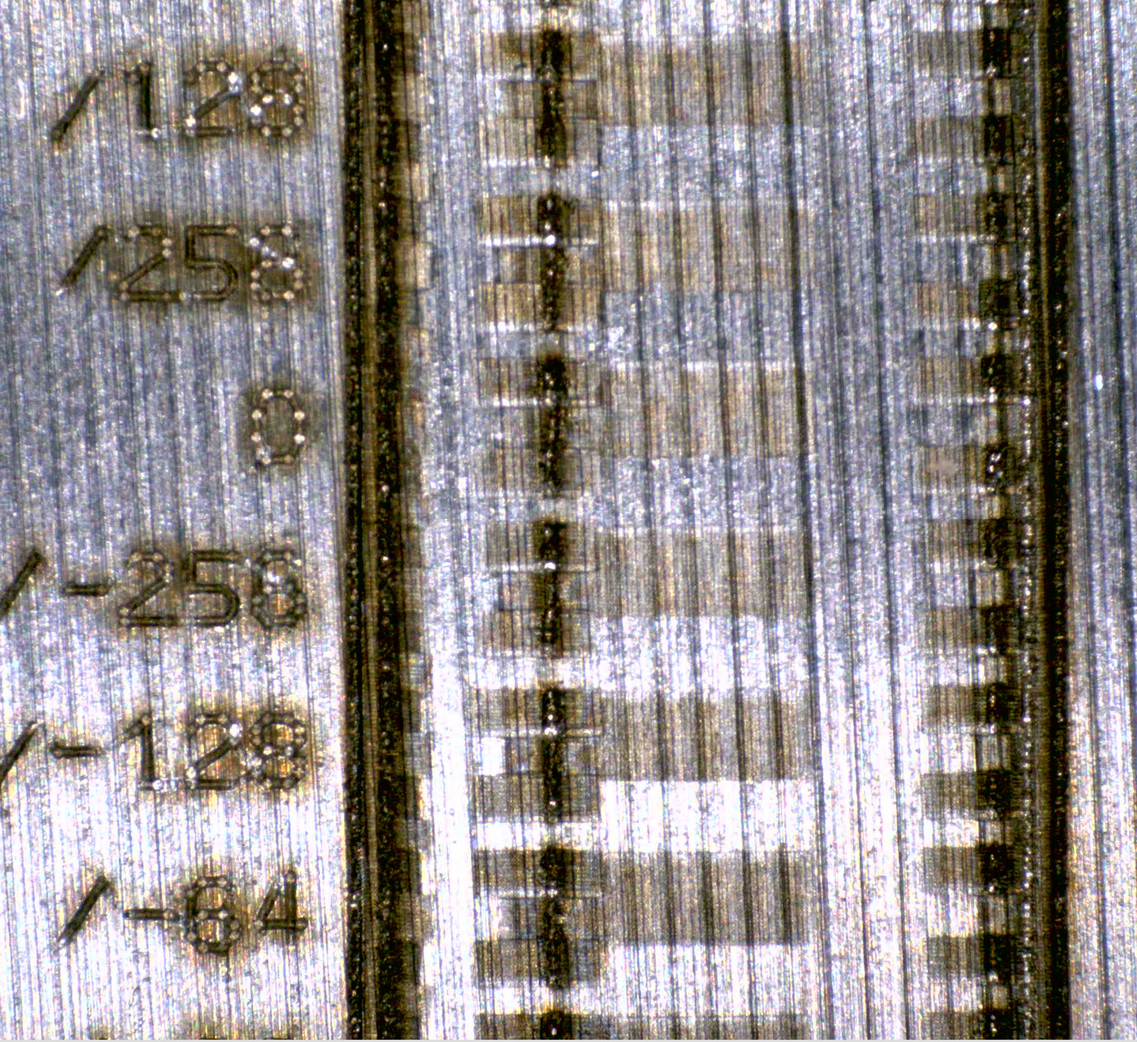
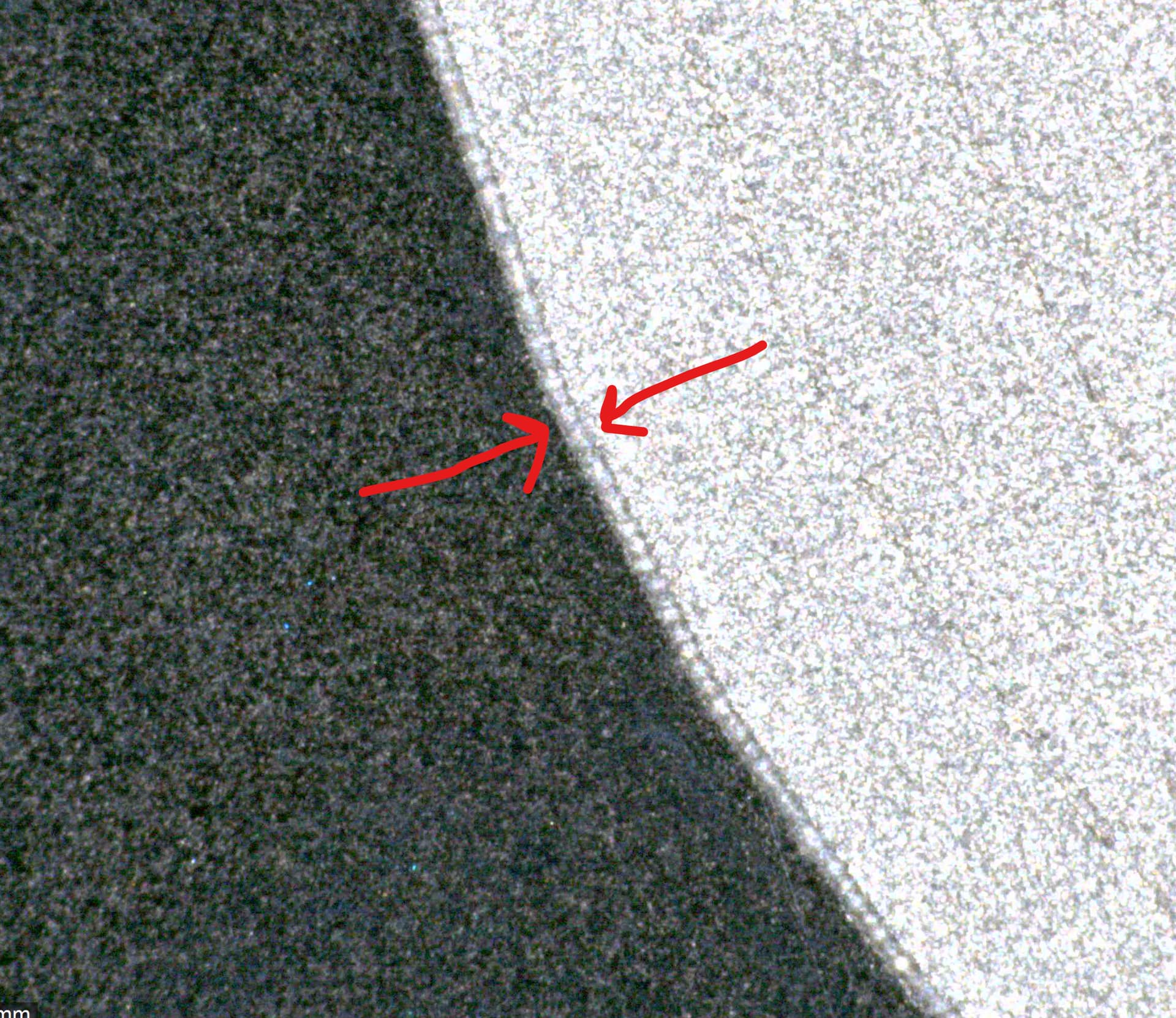
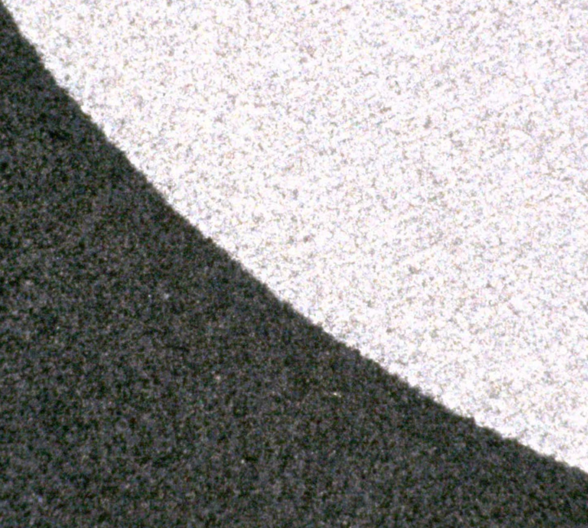
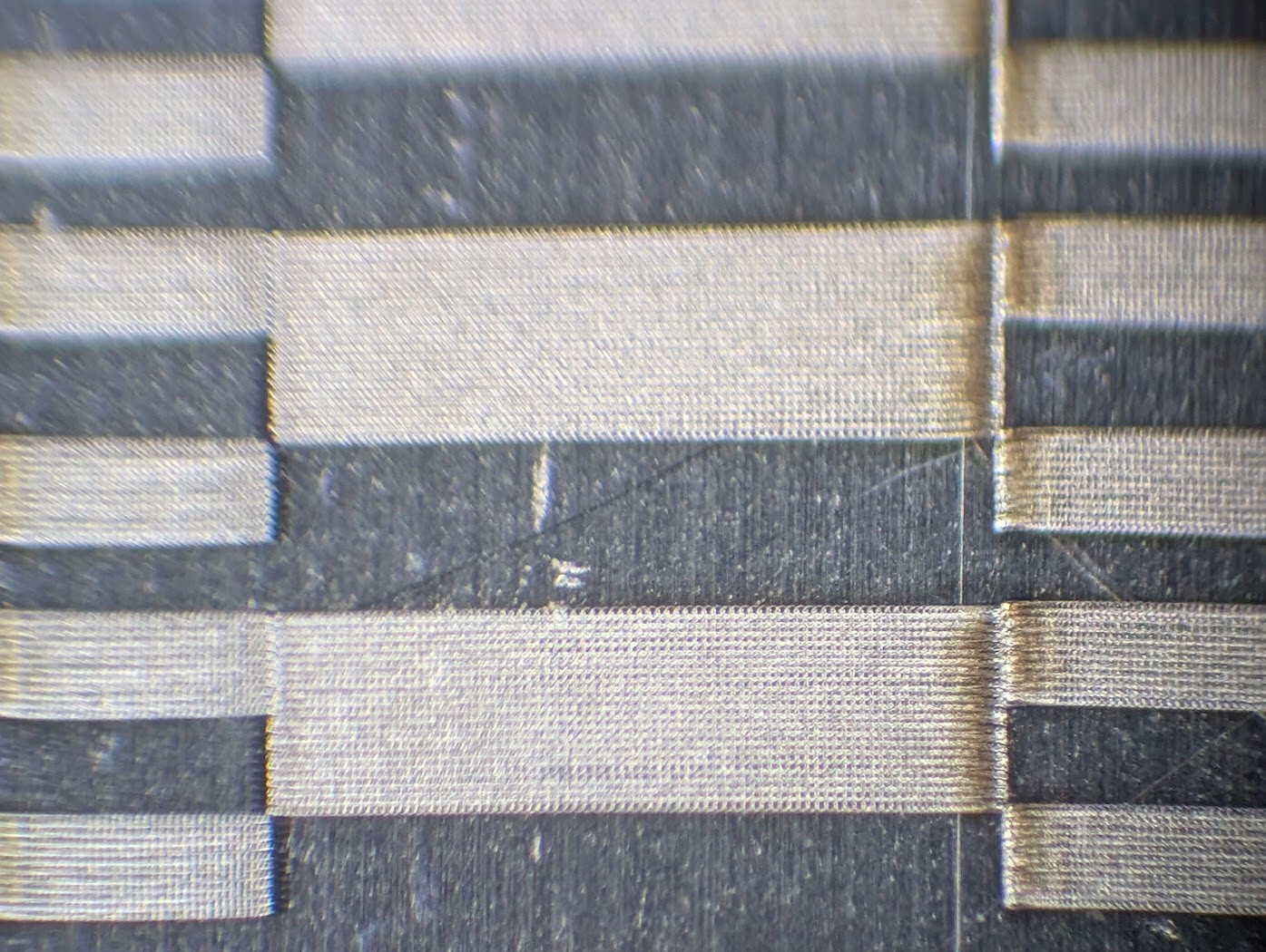
I got what’s shown below. The pulse freq/line interval were set up to space the pulses out at just a bit less than the spot size, minimal overlap. The second photo zooms in and is more telling, one side has pulses bunched up and the edge appears thicker because there are several pulses fired on top of each other as the mirror starts from a standstill. Now… ok, I’m not sure what is happening, that should be the trailing edge, not leading. The thick center bar is left to right, and I don’t think I 180’ed the pic. That should be trailing edge, and I thought there was no prob on trailing because the fire command stops first, immediately ceases the pulsing, but the mirror was just told to keep moving at CV to that point and overshoots, slowing or turning for the next thing it will cut, which shows nothing unless the Toff keeps the beam on too long.

Hmmm… wild theory here. Could the laser actually be scanning the opposite of what LB’s graphic is showing? The burn isn’t mirrored, but it wouldn’t necessarily have to be. If it’s mixed up, that would probably have to be inside LB not the laser. That is, the on-screen arrows and the command to the BJJCZ could be flipped. I’m gonna say this is “simpler” (for the purpose of Occam’s Razor principle of investigations) vs it braking to a stop before shutting off the fire command even though there’s more content on the line to fire for and it shouldn’t do that regardless. So I’d investigate that theory first.

The jog speed was higher than the cut speed, so this seems to show the mirrors have started on a bar on the left or right, did a rapid over the gap, then decided to come to a stop at the start point of a calibration bar instead of maintaining CV across the whole line.

Would anything change if this were two bitmapped images instead of Fill objects?

I do see the border bars are not running as a continuous bar from top to bottom as shown in the LB project. Both left and right bars are created as a narrow vertical bar running the whole height, with a red and blue copy superimposed. The one on the left has offsets that correlate with the blue test bars inside which run right to left. The one on the right has offsets that correlate with the red bars inside, which run left to right.

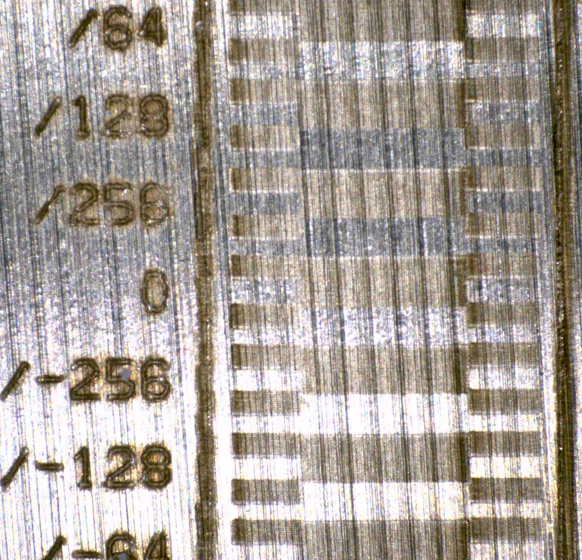
OK, what does that jagged border bar tell us? Let me think through that… take the bar on the left. Each line is always covered by an identical superimposed unidir of both directions (not bidir, which alternates left and right from line to line). Why is it jagged? Let’s think about the bar on the left, specifically its right edge. It reaches further to the right. It syncs up with the occurrence of the narrow side dashes, not the thick center dash. That’s blue layer, supposed to be moving right to left. There’s ALWAYS more blue content to the right of that bar, so…

“the right edge of the left border bar starts sooner if the prior blue content ended closer to it” (??!)

Am I thinking of it wrong, that it’s the thick red dash content causing it? Doesn’t seem possible, the period of the defect lines up with the narrow blue dash, not the red.

The left border bar’s LEFT edge reaches out further to the left when there’s no blue right-to-left dash on its right. Let’s phrase it as “why is the left edge of the left border bar further to the left specifically when there’s not a blue (right to left) dash nearby to the right? There is always more right-to-left dash to the right in both cases, it’s just further off”.

Now, I can’t entirely say whether this was the left-going pass staying on too long, or it’s a right-going pass starting too soon on the neighboring line above it. Neither of those make any sense to me. And the right edge of the right border bar is VERY dead-on.

This is a very small error at 5000mm/s. It could actually be a numeric rounding error somewhere, rather than a true Ton/Toff calibration. That sounds plausible, maybe the only possibility. Such a rounding error could be in the BJJCZ hardware or just in LB.

I’m a low-level hardware/firmware guy, does that make sense? Yeah, actually, it could definitely happen. The whole XY galvo coordinate system is divided up into finite divisions- probably 16 bits for the whole field (310mm plus some overscan area for the mirrors to coast past the usable edge, that sounds essential for the driver to work right). About 4 microns resolution. But the beam’s start/stop or start/duration is time, not distance, communicated to the MOPA, That could have idiosyncracies in sync or time resolution in LB, the PC-to-BJJCZ link, the BJJCZ FPGA RTL, the BJJCZ-to-MOPA link or the MOPA’s FPGA RTL.

Like the BJJCZ-to-MOPA link is a UART for power and an on-off modulation wire. But the BJJCZ has a time resolution in its sysclock-divided-by-something in both its start point and duration, and they aren’t always the same. Like if this were a microcontroller (it’s an FPGA, but for a thinking exercise), a single pulse created by a PWM might have a duration as a whole number of 100MHz clock cycles, but the start point of the PWM pulse might be sych’ed to a 1MHz timer.

But more relevant, again, depends on implementation, but the MOPA’s got its own clocking scheme for starting and stopping based on a different clock, and they’re not sync’ed. So this could be time resolution and/or time jitter between the BJJCZ and MOPA clocks.

Yeah I’m definitely overthinking it, but sometimes that’s where the problem lies.


It would be trivial to find out whether your theory about the reversed directions is true - Increase the line interval to something like 1mm (just to make it take less time), drop the power to 0.5% (so you don’t burn the heck out of everything) and cut the speed to 50mm/sec. At that speed you should be able to see visually which direction it’s doing the rasters in.

One thing that might be causing issues here is that in LightBurn we use jump speed when moving between scanned shapes, and cut speed when actually engraving. It’s possible that the decel before you hit the shape edge is causing bounce.

From the file you posted, you haven’t overridden the timings. If you click the ‘Show Timings’ button you can set all the delays here to zero, and they don’t affect your global defaults:

Click the ‘Override Default Timings’ button and zero everything:

If removing the delays doesn’t change anything, you could set the jump speed to match the cut speed there, and that would rule out the decel as a possible cause.

One thing that might be causing issues here is that in LightBurn we use jump speed when moving between scanned shapes, and cut speed when actually engraving. It’s possible that the decel before you hit the shape edge is causing bounce.

Oh. Yeah these are filled rectangles.
Seems like this will be a meaningfully different test if run as two raster interpretations. This would line up much better with what we’re trying to cal for- that the bidirectional will have the leftgoing and rightgoing lines line up. And when you rotate 90 deg that the timing still makes the same image front the other direction that way.

Oh wow, I see I already did that! And forgot! Wow, I’m losing it.
Layer 5 and 6 are the red and blue fill layers copied over as one big raster for the leftgoing vs rightgoing. And they’re already configured in the print settings. I can’t wait to go back and revisit what this did.