With my 60W I couldn’t find the sweet spot with a 175 lens, had to go down to my 100x100. I think, though, quality of the board makes a difference, uniform thickness of the copper. I had some that would burn through in places and not even mark in others. Multiple passes made it worse.
This is curious… I though the pulses/s were based on frequency setting. At least that’s what my M60 MOPA manual states… I believe.
At what point does the increase in pulse rate change as power is increased? Where what is the limit. A 1.5kW fiber, pulses faster than my 60W a 100W or 300W fiber?
Why does the lens for 100W machine cost about 8 times that of a <100W machine if it’s only a faster pulse rate?
Machine has the same input frequency range.. ?
I thought I knew something about these.. 

1 Like
a pump diode (in this case 100W at 100%) pumps a active fiber (ytterbium doped) with energy, a given length of fiber has a given maximum capacity (0.75.. 1.. 1.5mJ) and a q switch / aom releases that energy at the set frequency from the fiber.
at 30W a 0.75mJ fiber can be fully charged at a rate of 40khz, if you set it higher you “release” a partially charged fiber and have less pulse energy
100W just charges the fiber faster, but the given length can only store a given amount of energy, pumping in more doesnt give you more.
mopa is a little different than just a q switched fiber laser you have two active fiber circuits.
one is low power (master oscillator) to “form” the pulse length (ipg type) and even shape (trumpf / spi) and feed that into the power amplifier that amplifies it.
but you wont get more pulse energy out of that, you just have more control of it.
a higher frequency at the same pulse energy increases the average pulse power, and since glass lenses absorb a fraction of it, it might be enough to heat them up and crack thats why you need the more expensive made from quartz or some low absorbing / expanding material.
100W Units are also more expensive because the type and thickness of fiber and optical splices, bragg gratings, isolators etc. used it different, you cant just shove 100W into a unit made for 30W without damage.
there are very few >200W Pulsed fiber lasers
all those 1…2..3kW cleaning lasers, steel cutting etc. are not pulsed. these are CW and output a steady beam that can be modulated
they have almost the same internals, minus the q switch / aom.
a real pulsed unit at that power level costs a fortune as you need the right kind of fiber that can handle a 1kW+ pump. but from what ive read they also just have around 1..5mJ, just at a higher frequency.
the focal spot diameter can be calculated here
most chinese fiber lasers have a 8 to 10mm beam coming from the faraday isolator (business end)
using a beam expander to widen the beam can decrease the focal point
but then you need a galvo that can handle the larger beam.
most galvos are not faster or better than the cheap ones, they just have bigger mirrors to handle thicker beams
the powers involved can be calculated here then
1 Like
Thanks for the explanation… gives me something to think about.
No kidding. I have noticed the frequency cutoff table is a lot different for the 100W compared to my 60W, possible explanation.
a friend who’s deep into this stuff mounted a galvo head on a CNC gantry so he can move it around to increase its working area. this way you can for example have the benefit of a 75x75mm lens over a huge 1x1m area on a standard unit.
i think this would be the better solution than using more pulse power and bigger area lenses, as a bigger focal point also decreases the quality of fine details or get stupid expensive really quick
lightburn doesnt support that feature tho, same as z axis for 3d engraving where the galvo has a third “focus” axis that can move the focal point up an down to engraved curved surfaces.
a cheaper but very slow alternative to it would be a stepper motor on the spindle that moves the head up and down, but still needs to be controlled while its running.
would be nice if lightburn supported plugins in python so people can mod it on their own
Yah.
One of the options I was looking at was a Galvo with a slide table. But the cost is higher than i really want to go, and the programming thru ezcad 3 is more complex. Trying to make this as simple of a process as possible.
Just got a guy local to me to do some testing. He was able to no problem use a 30W M7 JPT MOPA (175mmx175mm) to do a board for me. He figured out the settings and had it dialed in in like 2 hrs. The FR4 is a little charred but I am not too concerned about that, I can do some cleaning steps after if needed.
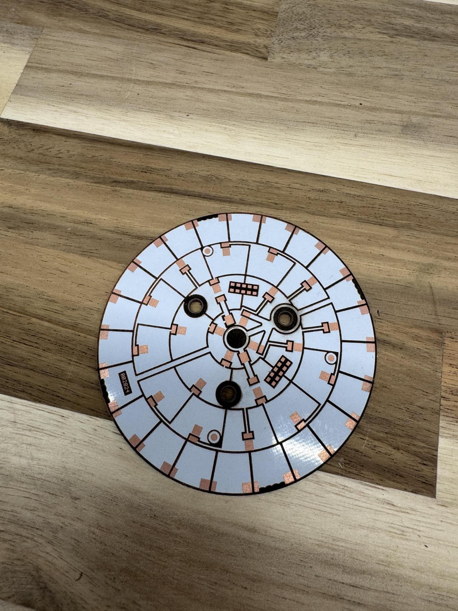
They recommend the uncommon “FR1” type (bakelite) core. I have only found it in single-sided. It doesn’t char nearly as easily as FR4.
Actually, I found I COULD do a slow, weak “clean up pass” that will actually burn off the char without cutting further and making new char. With either FR1 or FR4.
I tried this on my MOPA, but the fumes from the FR-4 type was too great for me. I have also see indications you shouldn’t lase the FR-4 type base material as it produces some type of toxic fumes. Don’t know the exact truth.
I found a web site many moons ago that has a chart (1/2 way down) on the differences between the type FR-1 though FR-4, such as the materials they use.
I’ve never seen any pcb that I could purchase that was an FR-1 type and doubled sided. So I assume there is no FR-1 doubled sided boards … ?
You obviously shouldnt lase anything without fume extraction.
even just the metal vapor thats produced can be harmful.
i once lased a sheet of beryllium copper (used for contact wipers), even just a meter long cut of it would create enough beryllium dust to become dangerous.
PVC is especially dangerous as it releases chlorine gas when being lasercut.
styrenes and urethanes release cyanide gas.
i needed some holes in a steel cabinet (around 1mm) and tought to use the laser for it.
but someone glued vinyl sheet over it and i forgot to turn on my fume extraction,it was a very short cut but i felt that for hours afterwards.
removing the foil made it a little safer
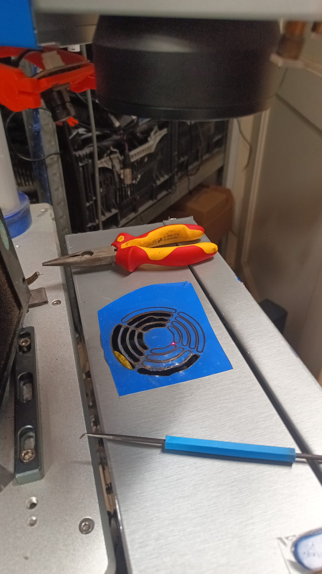
use hepa and activated carbon filter sheets glued to a 120mm fan sitting right next to it, cant get any cheaper than this. or just blow it outside
FR-4 is epoxy and glass fiber, epoxy is plastic.
but phenolic isnt better, its just missing the glass fiber part to make cutters live longer. burning it isnt good either
you can get FR-1 Boards (single and double sided) on sites like carbide3d
if your pcb chars, you need to move more to spread the heat.
prefferably full power, 2…3000mm/s and many passes in a order that makes the laser move all over the place. like “all objects at once” instead of one by one or flood fill"…and dont use wobble… this burns everything. good for drilling holes tho.
I guess they’re building these flying galvo head machines… There’s a couple being developed and at least one of them is in communications with Lightburn…
I seem to be missing something here… This is for an 80W and 100W machine.

I would expect as the q-pulse was shorter, there would be less time to pump up the fiber. This seems to indicate the opposite? I also notice the max pulse frequency is also changing, giving it more time to pump up between pulses.
I’m assuming you shouldn’t use a 4000kHz frequency if the q-pulse is shorter than 9nS if I want full available power.
Taking that into account, it still appears the threshold frequency should be going the other direction?
Can you clarify what they are saying?
Some general things I got from PCB etching:
High temp will delaminate the copper being removed. it will peel up and that puts it out of focus. this issue gets far worse when the copper gets thin. a strong removal pass that removes it completely won’t cause a problem, but it’s hard to get this right where the last pass removes a lot of copper but not overdo it and take a lot of core. going REALLY slowly will avoid overheating it.
You can also overheat thin traces.
The most heat-efficient removal is to use the focal spot size (0.030 on a 110x110 lens) as LI and as pulse spacing (speed/freq=0.030). This may not be an entirely smooth edge, but you can follow up with a smaller LI and smaller pulse spacing at a smaller Q-pulse
The best solution I found was to start with board artwork with copper all around the perimeter, then do an offset inward of the whole artwork, by a small amount. like 0.5mm even. without delete original. Then we do an Offset Fill will go between the original line and the offset line.
You want the offset fill to start at the copper trace edge and move away. This makes an isolating cut while both sides of the copper are still intact and it’s better at dissipating heat. And it’s a small total area so you can go slow.
Then I followed with an offset line (not a fill) to clean up exactly on the trace edge
Then a third offset, slightly less than the first Offset Fill, this time with “delete original”. Do a regular Fill across that to strip the copper with some aggressive passes and light finishing passes.
If you char the core, a pass with like 1/2 the LI, twice the freq, and very light q-pulse can actually take the black char off without making more.
1 Like