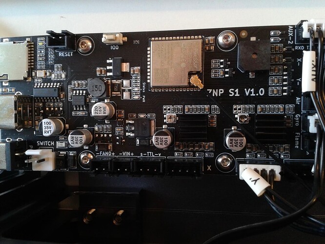
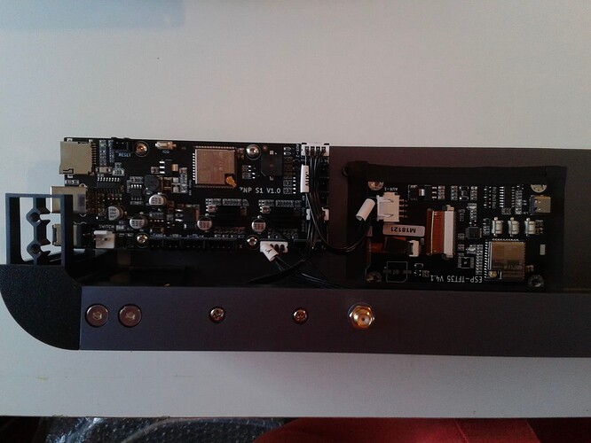
The reality is this likely at least somewhat true for all laser users, me included. ![]()
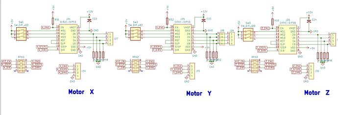
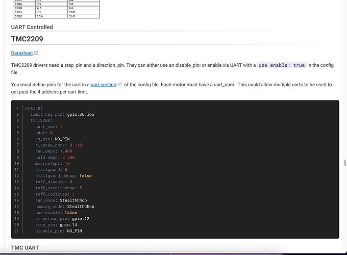
At the beginning, you don’t need to care about the UART stuff. Some TMC drivers can be tuned using UART communication, but according to your schematics, the UART line is not connected. They work in standalone mode then. Just configure them as usual A4988 drivers, like in the last example you linked.
I made the settings. But there are some lines I don’t understand.
For example;
laser:
pwm_hz: 2000
…
My laser 10W, Use for drive this. But, What is it PWM?
Also
shared_stepper_disable_pin: gpio.33
This row… “XYZ_EN” pin?
board: Elegoo Phecda 10W
name: Elego Phecda Mod by Fatih Sevinc
stepping:
  engine: RMT
  idle_ms: 255
  pulse_us: 2
  dir_delay_us: 1
  disable_delay_us: 0

axes:
  shared_stepper_disable_pin: gpio.33
  x:
    steps_per_mm: 80.000
    max_rate_mm_per_min: 25000.000
    acceleration_mm_per_sec2: 1000.000
    max_travel_mm: 400.000
    soft_limits: false
    homing:
      cycle: 2
      positive_direction: false
      mpos_mm: 150.000
      feed_mm_per_min: 300.000
      seek_mm_per_min: 1000.000
      settle_ms: 250
      seek_scaler: 1.100
      feed_scaler: 1.100

    motor0:
      limit_neg_pin: NO_PIN
      limit_pos_pin: NO_PIN
      limit_all_pin: NO_PIN
      hard_limits: false
      pulloff_mm: 1.000
      tmc_2209:
        step_pin: gpio.25
        direction_pin: gpio.26

  y:
    steps_per_mm: 80.000
    max_rate_mm_per_min: 18000.000
    acceleration_mm_per_sec2: 300.000
    max_travel_mm: 400.000
    soft_limits: false
    homing:
      cycle: 2
      positive_direction: false
      mpos_mm: 150.000
      feed_mm_per_min: 300.000
      seek_mm_per_min: 1000.000
      settle_ms: 250
      seek_scaler: 1.100
      feed_scaler: 1.100

    motor0:
      limit_neg_pin: NO_PIN
      limit_pos_pin: NO_PIN
      limit_all_pin: NO_PIN
      hard_limits: false
      pulloff_mm: 1.000
      tmc_2209:
        step_pin: gpio.27
        direction_pin: gpio.5

  z:
    steps_per_mm: 100.000
    max_rate_mm_per_min: 6000.000
    acceleration_mm_per_sec2: 500.000
    max_travel_mm: 50.000
    soft_limits: false
    homing:
      cycle: 2
      positive_direction: false
      mpos_mm: 150.000
      feed_mm_per_min: 300.000
      seek_mm_per_min: 1000.000
      settle_ms: 250
      seek_scaler: 1.100
      feed_scaler: 1.100

    motor0:
      limit_neg_pin: NO_PIN
      limit_pos_pin: NO_PIN
      limit_all_pin: NO_PIN
      hard_limits: false
      pulloff_mm: 1.000
      tmc_2209:
        step_pin: gpio.18
        direction_pin: gpio.19

a:
    steps_per_mm: 100.000
    max_rate_mm_per_min: 1000.000
    acceleration_mm_per_sec2: 200.000
    max_travel_mm: 300.000
    soft_limits: false
    homing:
      cycle: 1
      positive_direction: true
      mpos_mm: 150.000
      feed_mm_per_min: 100.000
      seek_mm_per_min: 800.000
      settle_ms: 500
      seek_scaler: 1.100
      feed_scaler: 1.100

    motor0:
      limit_neg_pin: NO_PIN
      limit_pos_pin: NO_PIN
      limit_all_pin: NO_PIN
      hard_limits: false
      pulloff_mm: 1.000
      tmc_2209:
        step_pin: gpio.16
        direction_pin: gpio.15

spi:
  miso_pin: gpio.12
  mosi_pin: gpio.13
  sck_pin: gpio.14

sdcard:
  cs_pin: gpio.15
  card_detect_pin: gpio.35

control:
  safety_door_pin: NO_PIN
  reset_pin: NO_PIN
  feed_hold_pin: NO_PIN
  cycle_start_pin: NO_PIN
  macro0_pin: NO_PIN
  macro1_pin: NO_PIN
  macro2_pin: NO_PIN
  macro3_pin: NO_PIN

probe:
  pin: gpio.36
  check_mode_start: true

macros:
  startup_line0:
  startup_line1:
  macro0:
  macro1:
  macro2:
  macro3:

user_outputs:
  analog0_pin: NO_PIN
  analog1_pin: NO_PIN
  analog2_pin: NO_PIN
  analog3_pin: NO_PIN
  analog0_hz: 5000
  analog1_hz: 5000
  analog2_hz: 5000
  analog3_hz: 5000
  digital0_pin: NO_PIN
  digital1_pin: NO_PIN
  digital2_pin: NO_PIN
  digital3_pin: NO_PIN

start:
  must_home: false

laser:
  pwm_hz: 2000
  output_pin: gpio.32:high
  enable_pin: NO_PIN
  disable_with_s0: false
  s0_with_disable: true
  tool_num: 0
  speed_map: 0=0.000% 1000=100.000%
  off_on_alarm: true
The laser is driven by a PWM signal. This defines the power of the laser module. It’s the electrical signal that is used to control it. Google PWM to see how it works, in this case it’s driven at 2000 Hz. That should be ok, but you might need to test. Sculpfun lasers have lower frequencies, like 1500Hz, the default of Fluid is 5000Hz.
Yes, that’s the shared enable pin.
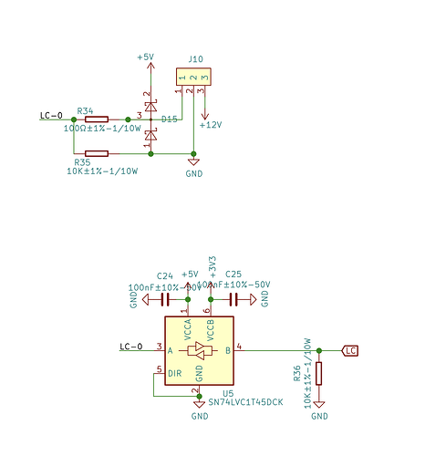
I asked the company about the PWM value. I hope he answers. Also, I couldn’t see the coolant and mist fan pins in the diagram.
Also, are my pulse settings correct?
   engine: RMT
   idle_ms: 255
   pulse_us: 2
   dir_delay_us: 1
   disable_delay_us: 0
The engine in x axis is → 42HD4027-02
Usually, there aren’t any. At the DLC32, it uses one of the I2C pins, if I remember correctly. But you could choose any pin that is available to control a relay. Otherwise, don’t define those pins.
I use
stepping:
  engine: RMT
  idle_ms: 25
  pulse_us: 4
  dir_delay_us: 0
  disable_delay_us: 0
  segments: 12
successfully with my Sculpfun S30 boards.
That’s not an answer to that question. This is always the case. You wanted to know the PWM frequency, not the values controlling the duty cycle.
Start at the heading “Duty Cycle” in this article.
Also, it’s nothing to worry about. In Fluid NC you will have access to the Base Frequency… Line 2: pwm_hz
… and the Power Scale or Line 8: speed_map
Note: The example linked recommends S Value Max = 1000 the same as speed_map.
I changed the step settings. Because my original machine settings were like this.
board: Elegoo Phecda 10W
name: Elego Phecda Mod by Fatih Sevinc
stepping:
  engine: RMT
  idle_ms: 25
  pulse_us: 10
  dir_delay_us: 1
  disable_delay_us: 0
Maybe use this setting for laser (spindle speed)
“$30=1000.000 (Maximum spindle speed)”
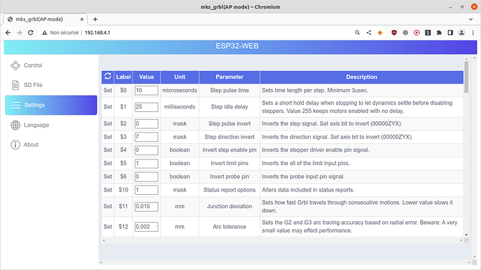
Elegoo Phecda 10 W default factory settings
$54=12345678 ()
$52=12345678 ()
$0=10 (Step pulse time)
$1=25 (Step idle delay)
$2=0 (Step pulse invert)
$3=7 (Step direction invert)
$4=0 (Invert step enable pin)
$5=1 (Invert limit pins)
$6=0 (Invert probe pin)
$10=1 (Status report options)
$11=0.010 (Junction deviation)
$12=0.002 (Arc tolerance)
$13=0 (Report in inches)
$20=0 (Soft limits enable)
$21=0 (Hard limits enable)
$22=0 (Homing cycle enable)
$23=5 (Homing direction invert)
$24=300.000 (Homing locate feed rate)
$25=1000.000 (Homing search seek rate)
$26=250.000 (Homing switch debounce delay)
$27=1.000 (Homing switch pull-off distance)
$28=1000.000 ()
$30=1000.000 (Maximum spindle speed)
$31=0.000 (Minimum spindle speed)
$32=1 (Laser-mode enable)
$41=1 ()
$47=1 ()
$46=1 ()
$102=100 (Z-axis travel resolution)
$101=80 (Y-axis travel resolution)
$45=0 ()
$44=0 ()
$43=0 ()
$42=0 ()
$50=1 ()
$40=1 ()
$100=80.000 (X-axis travel resolution)
$103=100.000 ()
$104=100.000 ()
$105=100.000 ()
$110=25000.000 (X-axis maximum rate)
$111=18000.000 (Y-axis maximum rate)
$112=6000.000 (Z-axis maximum rate)
$113=1000.000 ()
$114=1000.000 ()
$115=1000.000 ()
$120=1000.000 (X-axis acceleration)
$121=300.000 (Y-axis acceleration)
$122=500.000 (Z-axis acceleration)
$123=200.000 ()
$124=200.000 ()
$125=200.000 ()
$130=400.000 (X-axis maximum travel)
$131=400.000 (Y-axis maximum travel)
$132=50.000 (Z-axis maximum travel)
$133=300.000 ()
$134=300.000 ()
$135=300.000 ()
It is the same board I am using. It uses grblHAL not grbl.
I have resisted installing custom firmware.
If you feel you really have to, backup the original firmware first so you can go back if things don’t work out.
There is a lot more to the grblHAL firmware than the old grbl.
It looks very difficult. There is no telling. How is it compiled and installed?
Read GitHub - makerbase-mks/MKS-DLC32: MKS DLC32 motherboard kit, which is an offline engraving master control kit developed for desktop engraving machines. The hardware is equipped with a 32-bit high-speed ESP32 module, integrated WIFI function, and directly drives a 3.5-inch touch color screen; it can realize fast engraving and WEB web pages. Control, mobile phone APP control and other functions.
check the board is actually an MKS DLC32, check board version number.
Using Windoze ? they have an ESP32 download tool, don’t know if it also backs up your current firmware ?
Firmware · makerbase-mks/MKS-DLC32 Wiki · GitHub
Remember the golden rule - measure twice cut once, read carefully, else you might brick it and be buying a new controller. If not totally sure, don’t do it.
What is the advantage?
Your original question was
… Can I install custom grbl 1.1 firmware on my machine? …
short answer, no,
long answer, grblHAL firmware belongs in this board,
Not knowing if Elegoo has customised the MKS-DLC32 hardware or grblHAL firmware, my safe answer is don’t upgrade your firmware.
Email the manufacturer for information.
The device is adapted from mks. Only esp pins were used directly to avoid using 74HC.
