I’m using a Falcon 2, GRBL, with Lightburn. For the past 2 years, I’ve been trying to fix a problem that makes it very frustrating to use this laser, and I am frankly at my wits’ end. That is why I am appealing to you for help - I have been lurking this forum and have seen it provide amazing input!
TL;DR
Not the usual “circle no meet. belt loose. what do?”. Consistent 1mm circular imprecision in two quadrants only, after troubleshooting the usual suspects.
The problem
When cutting a simple circle, there is always slight aberration - it turns ovoid - in 2 quadrants. Always the same 2 quadrant - SE and NW.
On a 200mm diameter circle, it’s a -1mm aberration, producing a 199 mm diameter at 135° and 315°. But there is no contrary aberration where it would produce 201mm diameters at 90° rotated from the aberration. What!
This means that the very thing I use a laser for - precision - eludes me and “complex” builds involving anything circular are impossible.
The problem occurs at any speed, and only when both X and Y motors have to move together. In rectangles, precision is always top notch both on the X and the Y axis.
What I’ve tried
ensured that no cables on the gantry, head, etc were restricting movement
ensured that motors did not suffer any irregular tensile resistance or blockages along the entire beltway by turning off the machine and moving the gantry and head by hand and carefully feeling the resistance
ensured safe material placement. material is being held so tightly to the honeycomb by pure Chinesium magnets that it is impossible for it to move.
troubleshot belt tension. As there is no precise manufacturer information on this beyond a video, and extremely contradictory information about it on the internet, I ended up with what “felt” right to friends of mine from the CNC/milling community.
performed a titlt test according to the video by Mike. gantry moves freely and both sides of it touch the end simultaneously.
troubleshot backlash with a CNC precision clock. The backlash is (20 measurement runs) below the margin of error for the precision clock (0.01mm).
calibrated and tested single-axis precision. After calibration, over 20 measurement runs, rectangular precision over 200mm and 300mm each is within the margin of measurement error with digital calipers measured on the material cut and and precision clocks measured on the head (0.01mm).
ran test cuts at different speeds, sizes. The problem is always present.
tried different LightBurn versions and PCs
asked people from CNC machine manufacturers whom I know for input. They suggested running the cut in reverse to see if the quadrants where the problem occurs change - but then what?
The problem has been present since day 1 of operation and has not deteriorated. It was obviously worse out of the box before calibration and the above steps, but I cannot get beyond the current aberration rate.
I know that marketing is marketing and that Creality’s advertised 0.1mm accuracy may be wishful thinking on an entry level laser. But 1mm is an order of magnitude worse. Am I asking too much? Does anyone have further pointers or a snap epiphany?
If it is not backlash. and only bad in 2 quadrants, then I would suspect a computational error (rounding?) in the laser controller.
Is this graphical quadrants or table quarters? Lightburn is designed to operate in Quadrant #1 (+X, +Y). If table, it could be a mechanical frame or alignment issue.
Have someone work up a GCode 200mm circle using circular arc (IJK) programming to see if that changes anything. That would be a different type of program calculations for the circle.
There are two positioning concepts, repeatability and accuracy. It is possible for one to be bad and the other not.
Everything I said here is based on semi-educated guessing.
Definitely not the case for GRBL descendants, particularly for any shape that fits on a Creality platform, because IIRC the firmware uses at least single-precision floats. Which is not to say Creality hasn’t changed something for the worse, but it’s way down on the list below all the mechanical problems inherent to diode laser machines.
I like the circular arc test, because it’d be a one-liner. Gotta sleep on it, though …
Scale it uniformly to fit the platform and run it as fast as it will go in Line mode with optimizations turned off and power set to mark a sheet of cardboard. Any differences from the design will be informative; a photo will let us look over your shoulder.
The beam spot is usually not square. What wattage do you use? Did you measure each dimension? You can do it using the line spacing test in each direction.
Also take a picture of the beam spot a few meters away on a wall. How does it look like?
Did you calibrate the distances based on cutouts (incorrect) or using engravings? If you used cutouts, you introduced the beam width into the equation.
Hi @MikeyH sorry for overlooking your question earlier. By quadrant I mean quadrants of the test circle. The position on the table didn’t seem to make a difference.
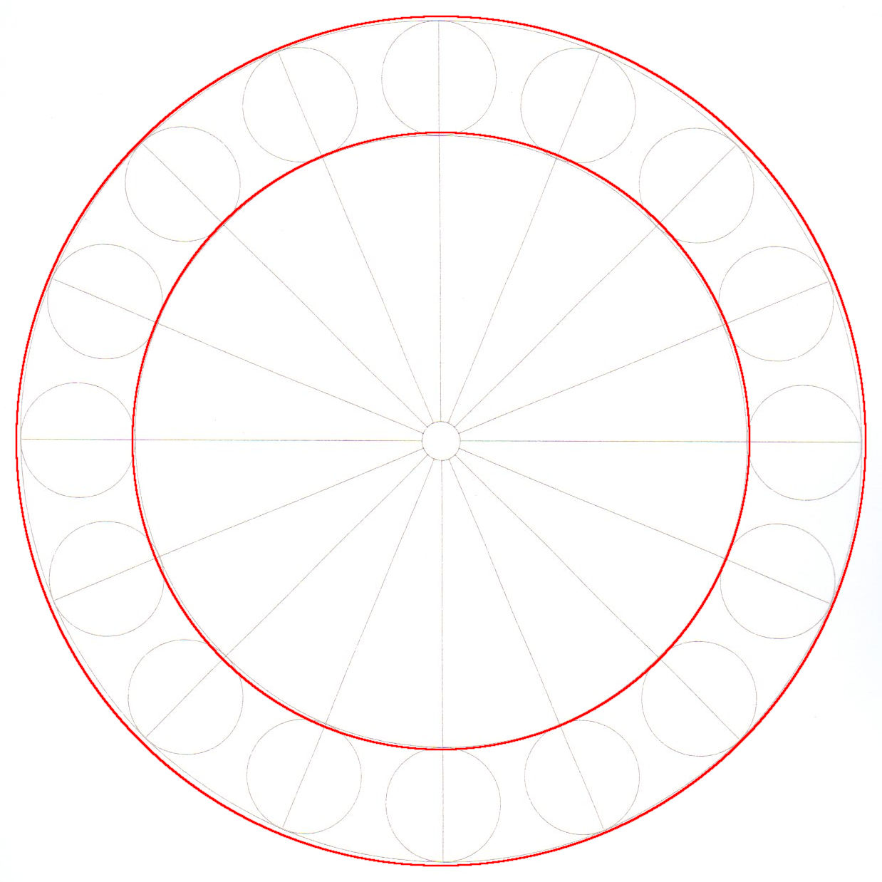
@ednisley I’ve run the file provided at 1700/10%. The file has a notice saying to turn Cut Path Optimization off, which I’ve done. Here are the results:
Then IMO the frame is very very slightly squished along a diagonal: the rear-right and front-left corners are a millimeter or two closer than the other two corners.
With an accurate metal tape measure, measure between the near sides of the recessed corner screws to get an idea of the frame squareness. The two diagonals should be spot on; if they’re not, that’s the problem.
A good metal rafter or framing square will give you an idea of the angular error inside each corner. You want the biggest square that fits inside the frame, because you’re looking for a millimeter or so of error across the machine frame.
@ednisley thanks so much for holding my hand and walking me though this. you people are godsends. I’ll grab a 400mm framing square and report back - please allow a few days for me to come back to you.
Using a joiner’s framing square, I was able to determine 1.5mm lateral deviation from the right angle over 400mm distance, at the front right corner. On the front left, that is much less pronounced.
Unfortunately, sometimes we find a slightly … dented … egg in the carton.
Although the frame members should be manufactured properly, we’ve seen misplaced screw holes and bent brackets. It will be worthwhile to take the frame apart and put it back together while examining the holes and measuring all the angles: perhaps you must file a badly drilled hole into an oblong to permit some adjustment where a perfect frame member wouldn’t need any.
Now that you know what to look for, however, you can verify your (re)assembly and check the results when you’re done.
I’ve got two items in this my collection here that may help but sounds like you’re addressing with your work. Head tilt and gantry square. I had to do both to my Falcon2 Pro 40W so I put these informational posts together.