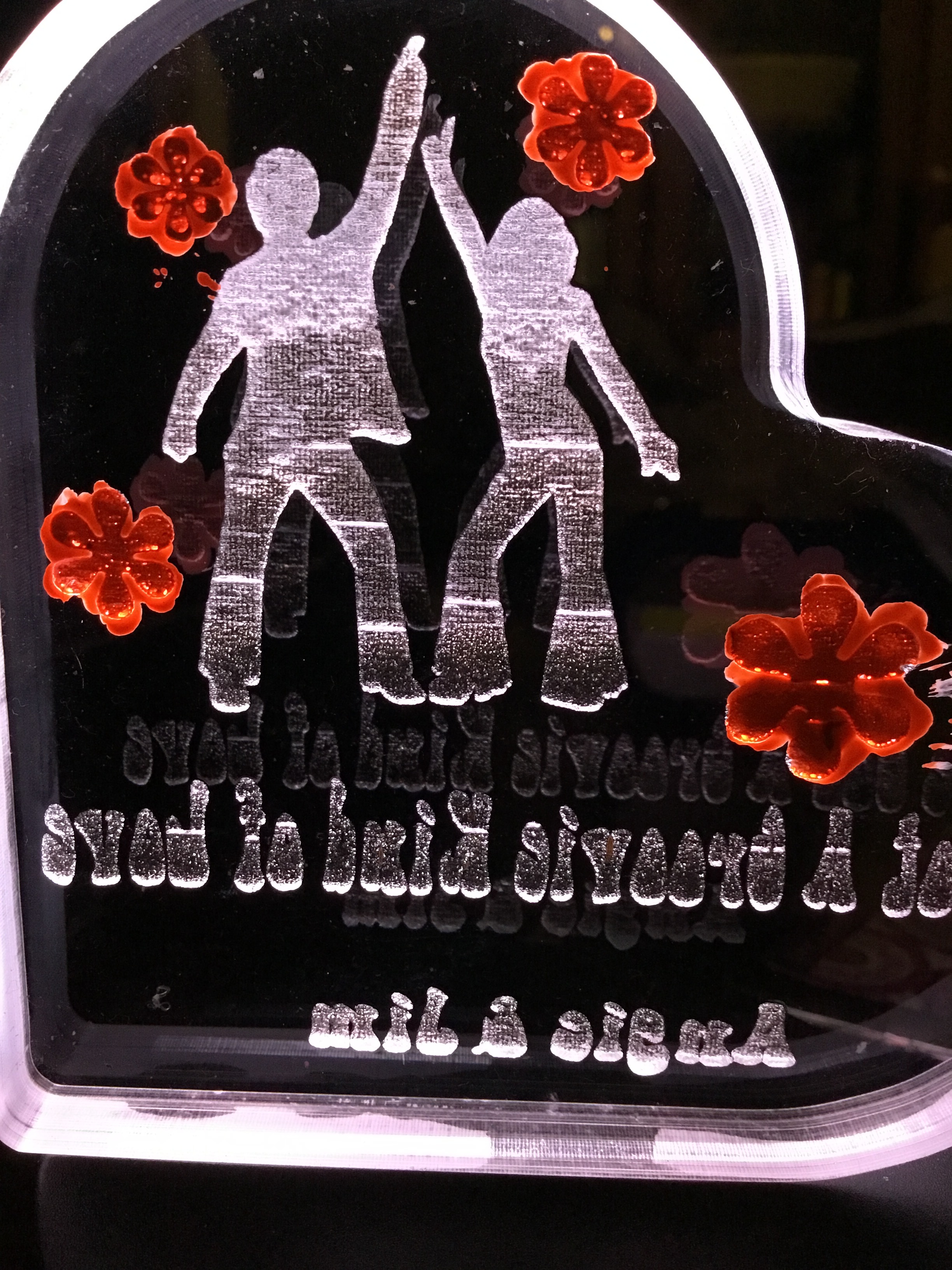
I am playing with engraving cast acrylic. I did some small pieces with primarily text and they came out great. Doing graphics where there is a large area that gets engraved, Im seeing lines left and right. I have tried different power and speed settings. Im running one now at 300 lines/inch.
If you can attach a photograph, it would be helpful. There’s a characteristic with engraving to create large areas that could be described by Russ as “curtains.” It’s a variation of velocity, I suspect, and believe that’s how Russ has approached it as well.
He’s created a set of videos for which I have no reference in which he’s reversed the belt so the teeth are in contact with the drive pulley for a fraction of the original amount but I can’t recall if he found it to provide a solution.
If it is how I think it might be, it’s a challenging aspect of engineering. The teeth are perpendicular to the direction of travel, for obvious reasons. As a tooth of the belt approaches the matching valley in the pulley, the air has to be pushed out. It doesn’t happen instantly because of science and that delay changes the velocity of the nozzle.
I have an electric vehicle which is driven by a single rear wheel. The belt is what is sometimes called herringbone. The teeth do not engage the valleys in the manner described above, but rather “ease into” the pulley. The result is a self-aligning belt drive, certainly a useful feature, but it is also quieter than a squared off profile. The air under the teeth are “more gently” pushed out to the sides, in a progressive manner, rather than all at once.
I’ve attempted to contact the manufacturer without success. I had considered to purchase the necessary belt to perform some tests, by 3D printing a matching pulley, but the belts are quite stiff and designed for a minimum diameter pulley that is too large for our machines.
I’ve put my research on this project on the back burner.
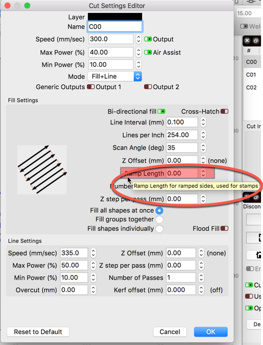
Ramp length is a reference to distance (sometimes time) that a power level would go from zero to maximum or from current setting to minimum.
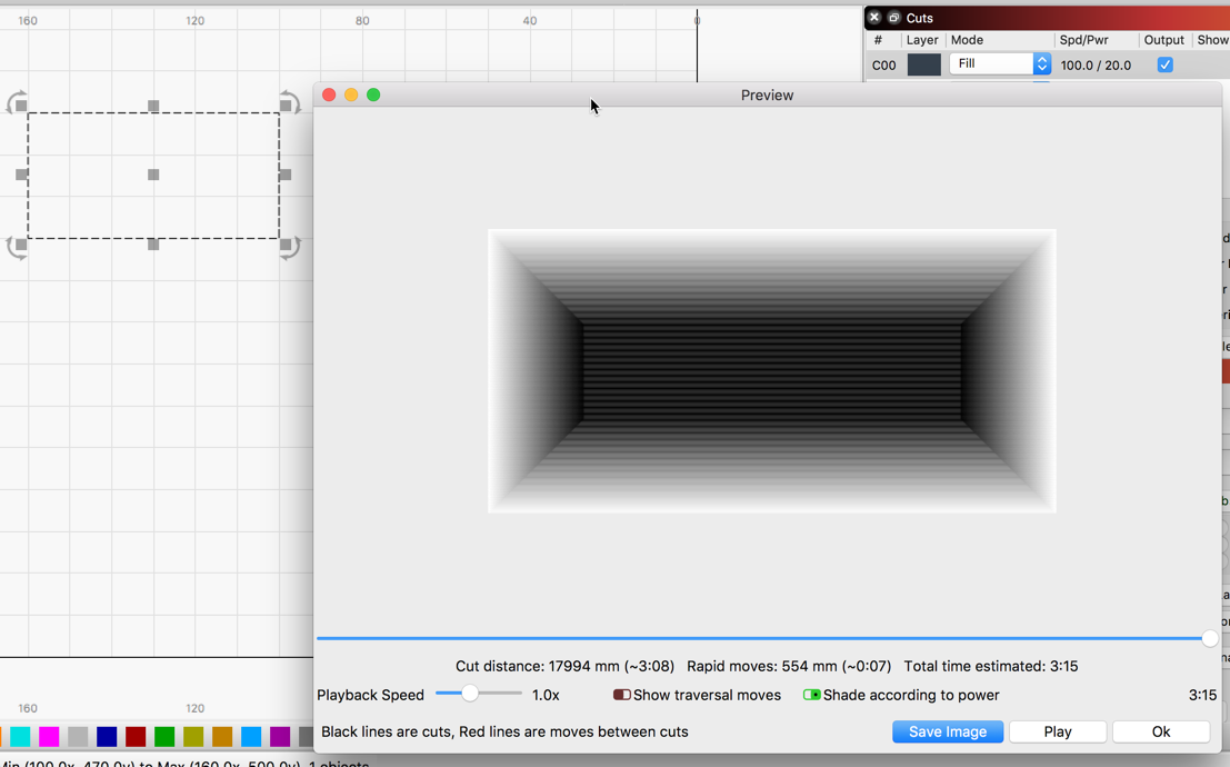
When hovering over this option, you will see this is used for stamp making were supporting the cut with “a ramp” may be required. This ramping effect is applied before and after the cut boundaries based on the number entered here.
You can see this when viewing in ‘Preview’. This example has a ramp of 10mm applied.