I’ve used the search feature here and over the ‘net in general, but coming up mostly empty. I have a 60W CO2 laser for my tool and a depth map created from an STL file. The process of creating depth maps is well documented, with so many variations involving free and paid software, with resolution options that defy counting.
What I’d like to be able to accomplish is to run the depth map through LightBurn in such a manner as to create a reverse depth (although I can invert the depth map if needed) engraving in a suitable material. The engraved area will take a pour to create an ersatz coaster multiple times.
What I’ve found here in the forum is an indication that this cannot be accomplished with a CO2 laser. There are plenty of posts and sites directing this process for a galvo laser.
Can this be done with a CO2 laser?
On the galvo side of things: I have recently received the Longer Nano Duo, which is still in the box. I suspect that it’s a galvo, with specs of 20W blue diode and 2W IR. It’s still in the box, because I’m getting re-acquainted with my CO2 and LightBurn after a long sabbatical and adding new hardware and new configurations to LightBurn is going to throw me off track.
However, if the Nano Duo would do the job, I can redirect for a suitable period of time.
Do the specs of the Nano Duo meet the requirements to chase down that method to create this object?
Not sure I completely understand the problem, or why a galvo would be a better option. Isn’t the solution just to convert the depthmap to a negative image using image processing software?
IMO, making the image correspond directly to what you want done will simplify the process, if only by eliminating one manual step in the middle I’d inevitably forget. The examples below are not inverted, for reasons that made sense at the time.
These responses are encouraging. I’m not sure why I did not consider a straight b/w bitmap burn, but the attached images provide useful guidelines.
@ednisley photo of non-linear results is not a show stopper, as the range of grayscale can be restricted as needed.
Here’s a related question, though. How would a material test coupon relate to a grayscale image burn? Is there an equivalent feature in LightBurn that I’m overlooking? I’d like to run a full range test, but then again, it’s not like I can specify power and speed values for any location within the depth map.
Some of my experimentation from a few years ago is coming back to me. I recall building a test sample manually, using MDF and recognizing that I can get quite deep in the material. It also lets me realize that there’s no correlation between a materials test and a bitmap burn.
It’s time to get some sample material and experiment again with grayscale panels.
Since my CO2 is an IR laser, two Watts is pretty meaningless, although the alleged portability may have value outside of the house. What can a 20W blue diode accomplish?
Vary the power from 5% to 70% (or 100% if you wish)
Vary the speed from 50 mm/s to 500 mm/s
Fire The Laser!
For each speed, the depth of the square for a particular power will roughly correspond to the depth of the grayscale image for that intensity.
Higher speeds will result in worse image resolution, because the power supply / laser doesn’t change intensity fast enough to keep up with tiny pixels.
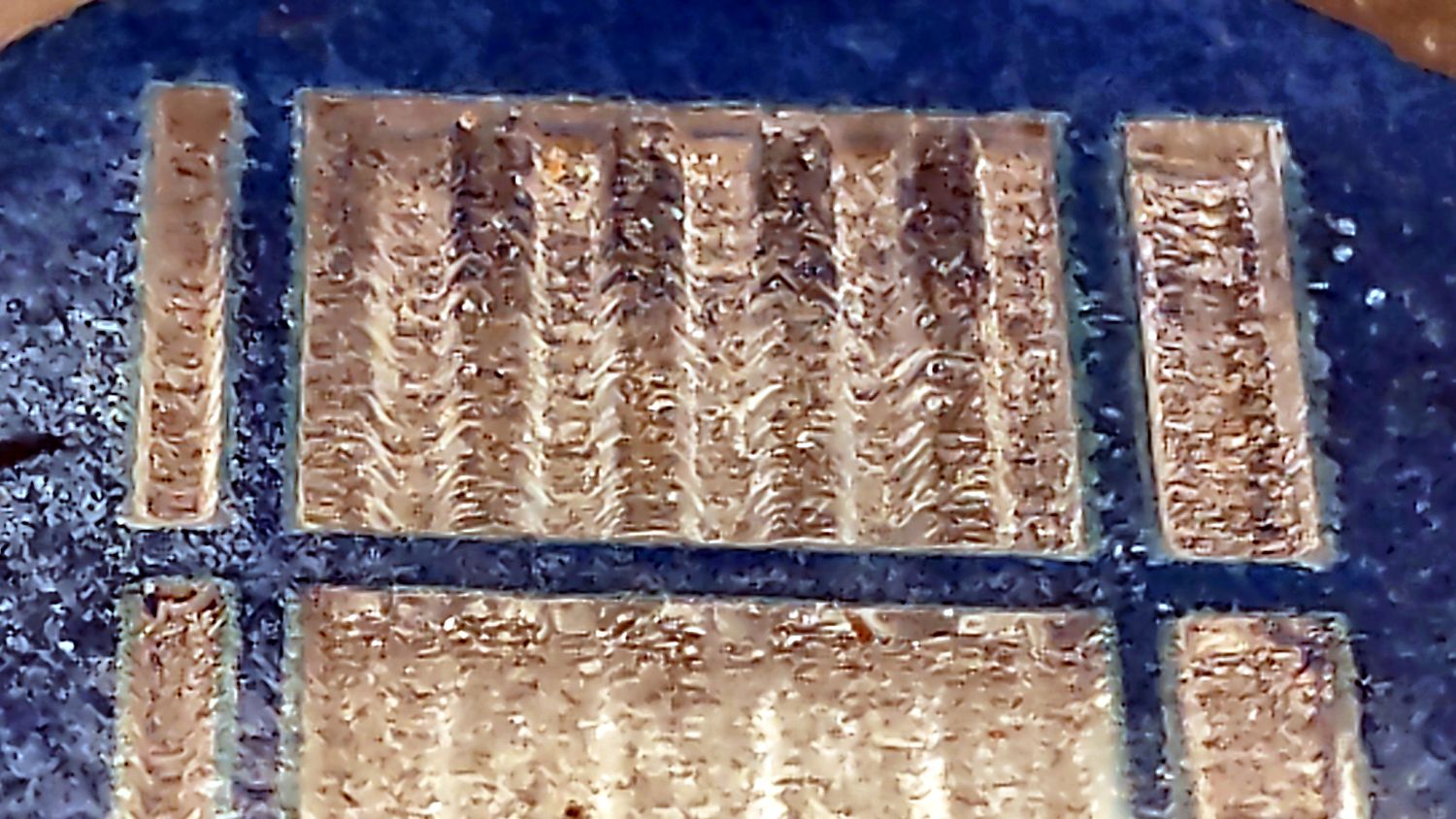
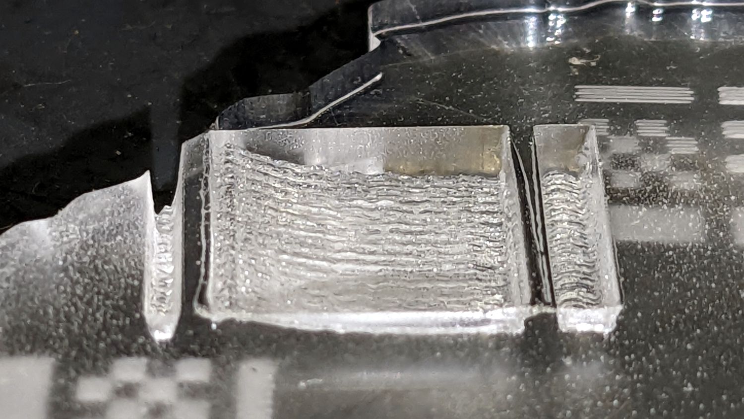
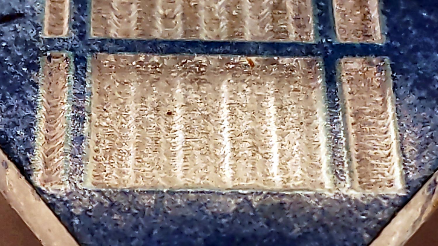
For example, the sine bar test pattern looks like this at 400 mm/s:
The sine bars are shallow and the rectangular bars on each side have sloped walls, showing why you want the speed as low as possible.
The dynamic range of the grayscale isn’t all that good: about six power doublings from 10% (lowest usable power) to 100%.
Galvos apply 255 single-intensity images, but you might be able to manually simulate that by hitting the same area with multiple (identical?) grayscale images. Each image has a limited dynamic range, but burning the same thing twice might increase the total effect (it won’t be double). Obviously, 255 images isn’t something you want to do by hand, but a (much) smaller number might be worth investigating.