HI there, this is my first post here. Very happy to have discovered Lightburn and the forum!
I am pretty new to Lightburn and to laser engraving/cutting in general and am planning to use my laser to augment my CNC router. I do a reasonable amount of engraving and graphics reproduction using wood and other materials so the laser is a welcome addition.
At the moment I am trying to use the laser to ‘engrave’ or etch paint to reveal an image, but I am having some issues. It will be difficult for me to explain so I will try to upload some pictures as well.
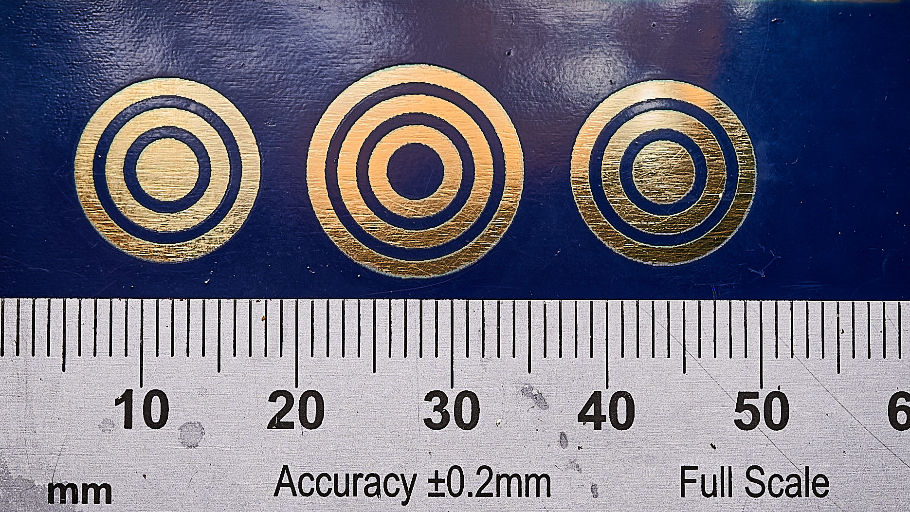
If I draw a circle, the one in the image is 3.9mm diameter (…ish), then add another four concentric circles offset at 1mm intervals and select preview or send it to the laser as a fill, I get an image which I would expect. The centre circle and two more alternating rings are engraved. If I add another outer concentric circle and repeat the process - in an attempt to create the inverse situation where the centre circle is not engraved and the engraving sequence is the opposite of the first set. My expectation is that the ‘width’ of the engraved bands would be pretty much the same (so the centre engraved circle in the first example and the un-engraved . However they are not.
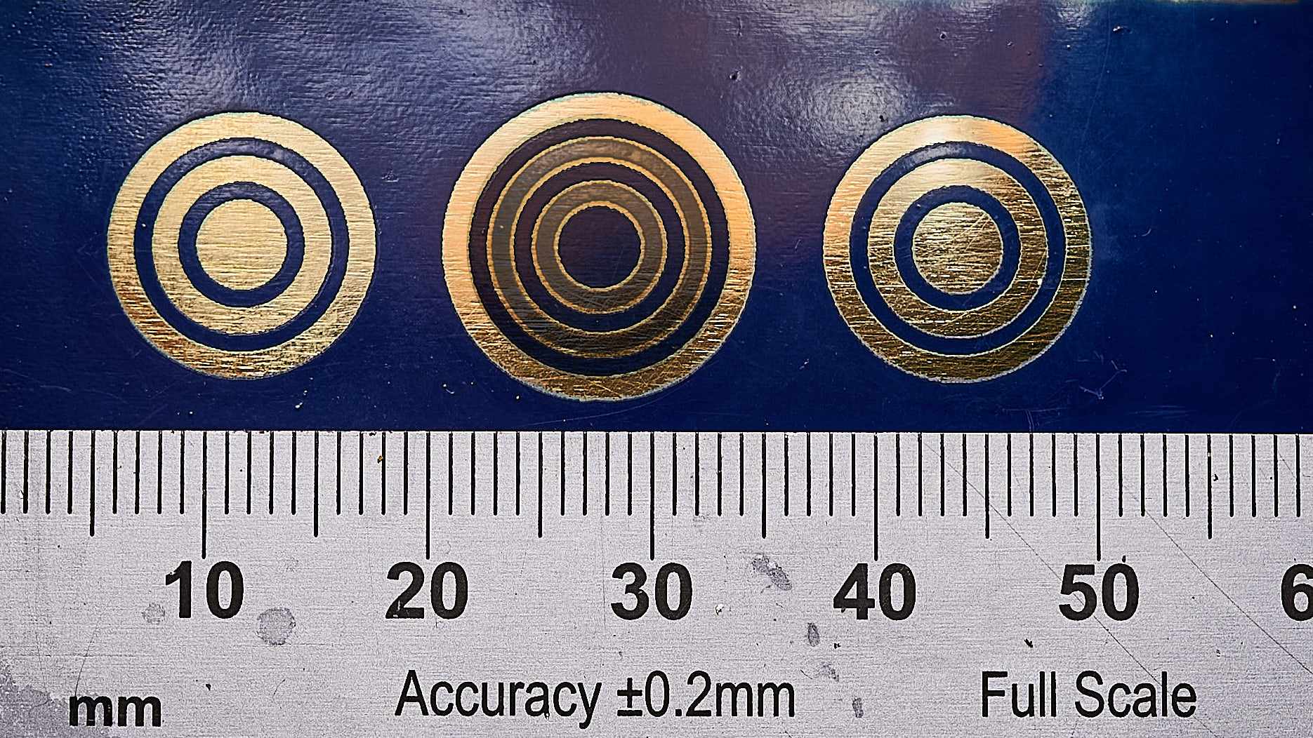
This is easier to see than to describe. The (hopefully attached) first image shows the initial concentric circles, the first and third set are exactly the same, the middle set have another ring added. The second image shows the first set of circles masked and overlaid over the second set (the areas with paint remaining appear more grey in colour and are a copy of the first set of circles)- there is a definite difference in the ‘width’ of each engraved ‘band’ otherwise there would be perfect match at the edges.
I expect that the difference in these two images is the effective ‘kerf’ of the laser - somewhere around 0.1-0.2mm. For larger images, this may not be much of an issue but at this scale it is a bit of a pain. I saw that there is a offset kerf function in Lightburn but I understand this only applies to vector cutting. Is there any way to control this in the engraving functions please?
The ruler in each image is just for scale. The material is painted brass and I am using the laser to remove the paint for metal plating or for acid etching. The paint is just acting as a mask for this purpose.
The laser is a Full Spectrum Hobby, 4th generation 40W upgraded with a Cohesion 3D board and I upgraded the belts/pulleys to 2GT. Lightburn represents a MASSIVE upgrade over the original software and I am really enjoying using it! Soo nice to have some software for the laser that just works!
Focus ring test.lbrn2 (62.9 KB)
