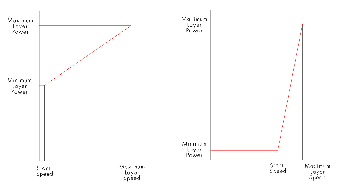
My understanding is that the “Start speed (mm/s)” parameter determines the speed below which the Min Power is used. Simple enough to understand, not a problem.
But I notice that under “Engraving parameters” there is an “X start speed (mm/s)” and a “Y start speed (mm/s).” What do these do? Min power is pretty much irrelevant when it comes to fills and images, so what function do these parameters serve? Could they pertain to something entirely different from the cutting “Start speed (mm/s)?”
The reason I bring this up is some strange behavior I’ve been getting with test cards. Folks may be familiar with the test cards that Thunder Laser has available to use. They get the laser to fire using a 0%-100% power scale at speeds slower than the “Start speed” using an ingenious trick. To test cutting power for speeds below 10mm/s they use “Fill” layers with a remarkably broad Line Interval. I’ve swiped this technique for some of my own test cards, and I’ve found a problem with the behavior. I’m trying to figure if the “X start speed (mm/s)” might have something to do with it.
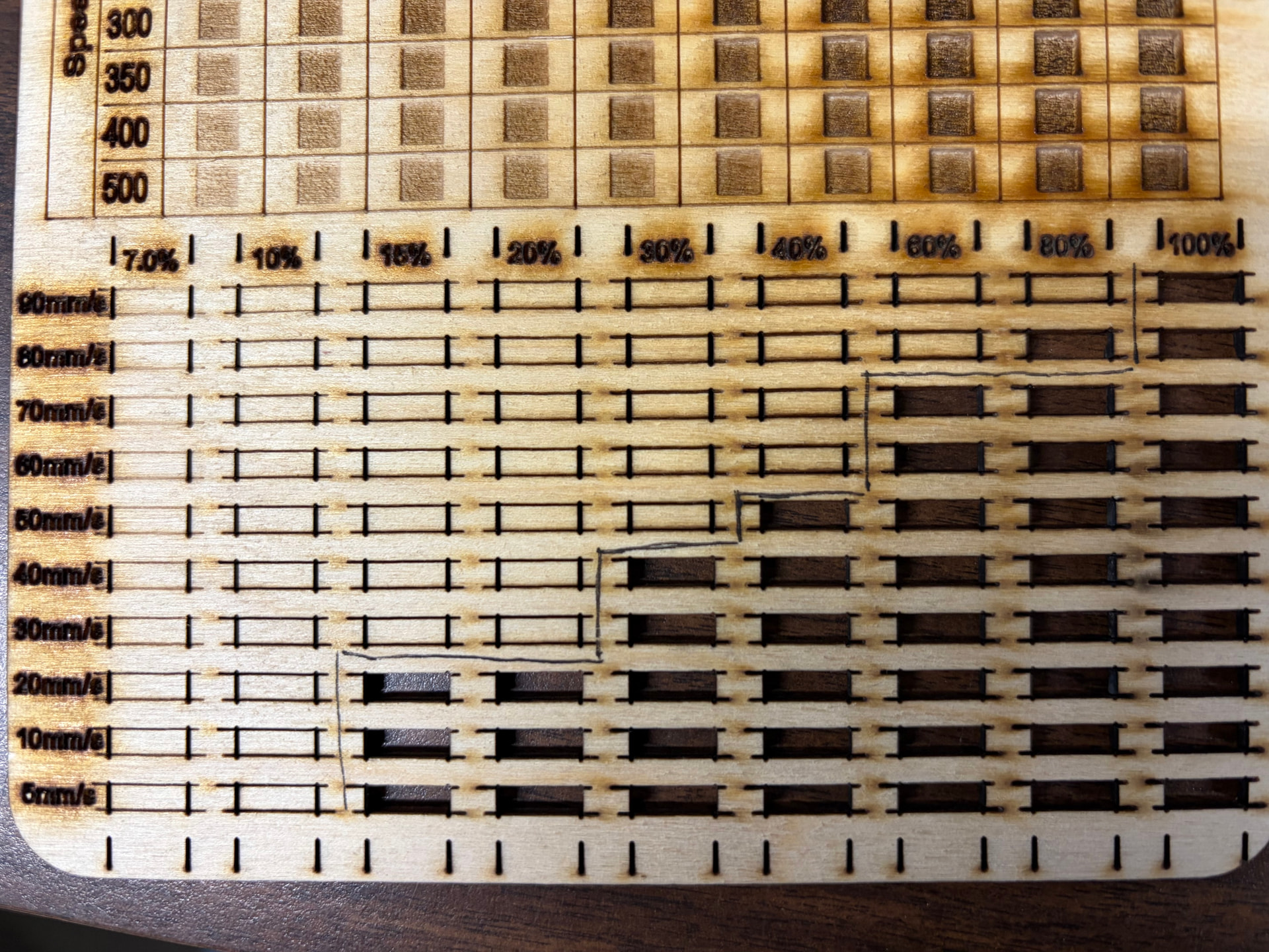
The problem I’ve encountered is that the power scaling on these fill layers masquerading as Line layers is clearly being scaled differently from the true Line layers. On test cards for multiple machines, you can see that the power seems to drop significantly at 10mm/s and 5 mm/s relative to the higher speeds. I’ve included a photo of two of these test cards to illustrate what I’m talking about.
On one hand, I could just go back to cutting off my test cards at 11mm/s and avoid this whole problem, but on the other hand, I’m now curious and want to understand what is happening. Could this have something to do with the “X start speed (mm/s)” setting under Engraving Parameters? What would happen if I started modifying that number? Or is this the result of some other aspect of how fills handle power scaling differently from lines, and could I modify that?
Here are two of my test cards if anyone wants to take a look at the setup.
I don’t think the Ruida applies any kind power control to scanned items. By definition, if you scan, the Ruida hardware applies overscan so the machine is up to speed by the time it reaches the image area. Results are no need to apply any kind of power control. Assuming a scan angle of zero or a multiple of 90 degrees.
Maybe a better question would be when are “engraving parameters” used over “cut parameters?” RDWorks seems to have a select icon for a cut operation, so I don’t know how/when they are used.
The define each as they can have different acceleration values. Say you’re doing a fill operation using flood fill… It can’t do the acceleration until it reaches the image as the fill is usually circular with the filled object.
I believe you to be correct about the functioning of the start speed. I think I figured it out and made this diagram.
Thunder warns you in the code that you shouldn’t modify these parameters, it’s possible that you get slightly different results from the RF or metal tube machine over a glass tube machine. You need to understand how they are using shape properties before you modify any of these.
If you attempt to use preview on your revised source, I get a bunch of warnings about minimum power being set to zero. I don’t get these from the original code, so something is not correct with your modifications. What this means is that Lightburn has an issue with these values and doesn’t know what to do with them… at least it thinks it’s not correct. Of course I’m running version 1.7 of Lightburn.
I agree here, but don’t think this was any way related to wobble. Most of their speeds are pretty slow.
My 2 cents worth, even if they don’t make pennies anymore.
Here’s another data point that has occurred to me. This is the test card I made for the Thunder Laser we have. Here, it’s inconclusive if we’re getting the same drop off for the 10mm/s & 5mm/s lines. I assumed that the phenomenon I’m addressing caused the stair step to drop off rather than progress further to the left, but now I’m not sure.
In one respect, Thunder Laser Ruida controllers work differently from any other Ruida controllers I’ve worked with. With a standard Ruida, the “Laser 1 Maximum Power (%)” setting under Vendor settings acts as a hard limiter. So let’s say I have my max power capped at 70%. If I run the laser at 70% power, I’ll get the same amount of power as I will if I run the laser at 100% power. The power slope is not changed, it’s just flattened at the max percentage. On Thunder Lasers, on the other hand, setting the “Laser 1 Maximum Power (%)” instead changes the shape of the entire power curve. In this case, if the max power is capped at 70% and I run the laser at 70% power, I’ll get 70% of 70%––roughly 50% of the power supply’s available power. While if I run the same laser at 100% power, I’ll get a true 70%.
It could be that this discrepancy could explain why Thunder puts out these “train track” test cards set up this way. It is entirely possible that they work correctly on their own laser machines but incorrectly in other lasers because of the difference in the Ruida controllers.
Perhaps I should try running the test card in my non-Thunder lasers with the “Laser 1 Maximum Power (%)” set to 100%. That might do the trick. I’ll report back with more info later.
That’s a good catch. It seems that in the Thunder Laser files, they set the minimum power on their layers to 0.1% power to avoid the warnings. I set my minimum powers to 0%. That’s the difference between my implementation and theirs.
Here’s another data point that has occurred to me. This is the test card I made for the Thunder Laser we have. Here, it’s inconclusive if we’re getting the same drop off for the 10mm/s & 5mm/s lines. I assumed that the phenomenon I’m addressing caused the stair step to drop off rather than progress further to the left, but now I’m not sure.
In one respect, Thunder Laser Ruida controllers work differently from any other Ruida controllers I’ve worked with. With a standard Ruida, the “Laser 1 Maximum Power (%)” setting under Vendor settings acts as a hard limiter. So let’s say I have my max power capped at 70%. If I run the laser at 70% power, I’ll get the same amount of power as I will if I run the laser at 100% power. The power slope is not changed, it’s just flattened at the max percentage. On Thunder Lasers, on the other hand, setting the “Laser 1 Maximum Power (%)” instead changes the shape of the entire power curve. In this case, if the max power is capped at 70% and I run the laser at 70% power, I’ll get 70% of 70%––roughly 50% of the power supply’s available power. While if I run the same laser at 100% power, I’ll get a true 70%.
It could be that this discrepancy could explain why Thunder puts out these “train track” test cards set up this way. It is entirely possible that they work correctly on their own laser machines but incorrectly in other lasers because of the difference in the Ruida controllers.
Perhaps I should try running the test card in my non-Thunder lasers with the “Laser 1 Maximum Power (%)” temporarily set to 100%. That might do the trick. I’ll report back with more info later.
This came up a few years ago.. One of the other Lightburn people has the same controller as mine, but a different firmware revision.
Mine, if I set the maximum power in the Ruida, it limits my input. It doesn’t scale the power as you describe, it’s like a speed limit. If mine is set to 50% and I set mine layer to 60% power, it truncates it at 50% pwm. The other firmware works as you describe.. So I guess there is different firmware on that machine.
You can read the firmware version as it boots, if you haven’t noticed.
Other than that, there isn’t much I can really say or do.. goes back to what @ednisley mentioned it’s not really addressed. Need to learn to read Mandarin Chinese I guess.
Well, I re-ran the test cards with more intuitive results. I ran essentially the same files except for two changes. I changed all the min powers from 0% to 0.1% to bypass the warnings. I also changed the “Laser 1 Maximum Power (%)” setting to 99% for both lasers. As you can see, there is no power dropoff between 20mm/s and 10mm/s like we had before. Presumably the way the Ruida firmware on these two machines handles power-scaled fills is to give a percentage of the difference between the “Laser 1 Maximum Power (%)” and “Laser 1 Minimum Power (%)”, while for lines they appear to give a percentage of the difference between the max and min power assigned to the layer. Well, I guess I’ve answered my own questions. Thanks everyone for the feedback!