Engraving Size Normal versus Inverted Engraving

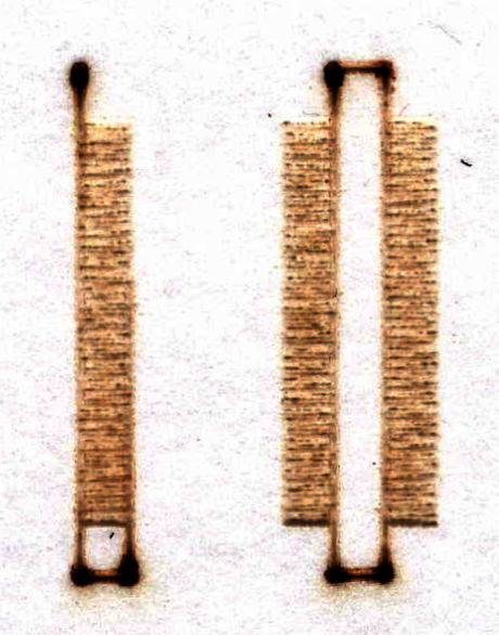
When I was Invert engraving on slate, I noticed that the areas I didn’t want engraved and to remain black got significantly smaller. In some cases, I can compensate by enlarging the area that I want to remain unengraved. Or even lowering the DPI if it’s a photo. Since I thought it was perhaps the substance I was engraving on, I explored what was happening with acrylic. So, let’s say you have a box, and it’s set to fill. The engraving will take place where you have the box and nothing outside of the box. Here’s an example of the filled box. (Clear acrylic placed on a blue background). A 1 and 2mm rectangle and square are shown here.

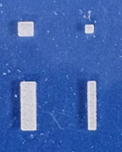
Now, let’s say you surround this box with another box on the same fill layer. You will get an engraving that excludes the box. An inverse engraving.

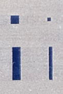
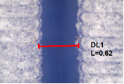
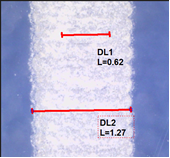
Now if you measure (I use a measuring microscope), the engraving width, the 1mm normal engraving is wider than 1mm while the inverted print the unengraved part is narrower than 1mm by a significant amount. You can see the difference in this example visually. Where this makes a difference is when lasering slate. The parts you want to come out dark are a lot smaller and sometimes disappear. I end up manually adjusting the vectors if using vector graphics or lowering the dpi if it’s a bitmap.

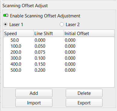
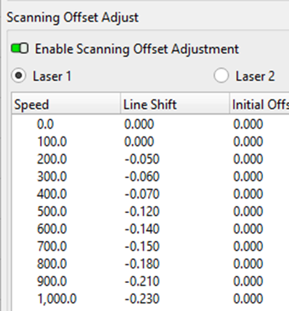
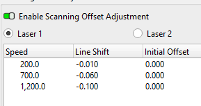
On my Nova 14 I adjusted my scanning offsets from 100 to 1000mm/s in steps of 100, tried slower speeds, and used single direction. Yet, the results are the same. The filled engraving comes out larger, while the inverse engraving comes out smaller than the box drawn. It’s not due to scanning offset issues, speed or bi-directional printing. I’ve also checked my axis calibration.

Don’t know why or if it’s adjustable. On a CNC router, I would have the ability to choose to cut Outside, On or Inside the line. Don’t think that’s an option here. But, if you have an explanation, that will expand my understanding.

Using 130Watt CO2 Aeon Nova 14S, Windows 11, Ruida Controller

Some things to consider …

What are the Scanning Offset table entries around the speeds for those rectangles. The ones for my machine look like this:

Assuming you’ve measured and set the table to match the machine, you may be looking at the inherent turn-on and turn-off delays of the HV power supply, which are vaguely specified at 1 ms; the rise and fall times are definitely not equal.

A 250 mm/s engraving scan speed will spread a 1 ms delay over a quarter of a millimeter, which will be obvious on a 1 mm feature; higher speeds will have more of an effect. Because the beam power (and its effect on the material) doesn’t vary linearly during the rise and fall, the effects won’t be symmetric and the scan line length will either lengthen or shorten compared to nominal.

A too-small Line Interval can also affect the width by over-burning the edges. Spacing the scan lines apart by about the spot diameter will produce much better results than, say, twice that density.

Although you’re not cutting through the slate, you can apply a Kerf adjustment to a vector layer to compensate for the beam width / spot size:

That’s roughly what you’d do on a CNC machine, with LightBurn normally running the beam along the middle of the vector and the Kerf adjustment offsetting it inside (negative) or outside (positive).

Skootching the beam over will move the visible effect on the slate, although you must keep track of which way the offset will be applied. LightBurn uses a simple line-crossing count to determine which way to adjust the kerf, so for very complex layouts you may be better off applying an Offset directly to the shapes that need it.

Because you’re not cutting through the slate, measuring the effect = width of the mark will be easier with a measuring magnifier. I suspect you already have one in a tool cabinet. :grin:

Doing tiny things requires getting all those adjustments spot on, so some careful fiddling may produce tiny-but-significant improvements.

Wow, thanks for the detailed reply.
Here’s my offsets:

I used a measuring microscope to help me set it. Here’s a photo from my microscope.

On line interval, I’m not worried about the top and bottom lines, but rather the ends of the line. I did test different line intervals and it did the same thing for vector engravings.
On setting the Kerf, I wish that was available for fill mode. Unfortunately, it’s only an option for the line mode.
On the delay’s that’s intriguing. What you said makes total sense. Is what you mentioned covered by these Machine Settings:

Let me know, and I can try different settings. I did try a slower speed, but I didn’t get a measurement, although visually it looked relatively the same. I can try that again if you think it’s a good idea and get a measurement.
Thanks again for your reply.

Those vary more-or-less linearly with speed, which is what you’d expect for a constant signal-to-beam delay. Looks good!

I’m always disconcerted to see negative numbers, but as long as they produce tidy alignments there’s nothing to fuss about.

Somewhat confusingly, Line Interval applies to Fill and Image layers, not to Line layers with vectors. So changing the Line Interval will have no effect on non-filled = vector = Line layers.

Because Kerf moves the beam perpendicular to the nominal vector path, it’s in the wrong direction for Fill processing.

The ends of the scanned lines get (slightly) trimmed by the Dot Width adjustment, but only by the diameter of the focused spot.

A while ago I did some timing measurements and here’s what you’re up against.

Given a test pattern with five 1 mm bars at 90% power separated by 1 mm spaces at 10% power:

The 2 mm line on the left helped identify which direction the head was moving on the oscilloscope trace.

Scanning that pattern at 100 mm/s moves the beam across each bar in 10 ms, about 10× the rise/fall time. The green trace shows the tube current at 10 mA/div:

The zoomed view on the bottom shows the current has a rather poorly defined rise time and a terrible fall time when controlled in variable power mode.

Conversely, the magenta trace is the digital L-ON signal that produces an abrupt fall time and a terrible rise time when switching the beam off and on without power modulation.

So seeing the “length” of a 1 mm feature differ depending on whether the laser is turning on or turning off at each end isn’t particularly surprising. The tube current absolutely isn’t the neat digital waveform we all expect from the crisp LightBurn layouts. :zany_face:

Bottom line: you can’t get the level of precision you want without measuring the results and manually pre-distorting the design to compensate.

Ruida doc is really sketchy and the verbiage (in general) does not match what you see in the controller settings. If you look those up in the manual for the specific controller in your machine and squint hard, I think you’ll find they’re delays for various output signals controlling fans / stack lights / feeders / widgetry, not the laser itself.

On the offsets, I started with positive numbers and the lines were moving the wrong way. So negative numbers aligned them. The Aeon Laser ships with LightBurn offsets (lbso file extension), so I checked those out. They were also negative. Of course I found this file after I set my own offsets. Here’s the setup from the factory:

Looks like the HV supply in your machine (now?) has about twice the delay as their reference standard.

Which confirms my suspicion: the settings shipped with any given machine were correct for some similar machine sold within the memory of those yet alive. :frowning:

Having slept on it, the Dot Width adjustment applies to images like the target I used, but isn’t available for ordinary Fill layers. Image engraving generally uses a dither pattern with discrete dots, where fixing the dot width makes sense.

I’m wondering if others are seeing this? If you can, can you laser engrave the following and see how it compares to what I’m getting?

Draw 2 1mm rectangles. Set 1 to fill (no line mode) and have the other invert fill (by drawing another rectangle around the 1mm rectangle and setting that to fill.)

Compare the width of the 1st rectangle against the width of the clear space of the second rectangle. Are you seeing the same thing I’m seeing with your laser? The engraved rectangle is larger than the unengraved area of the second.

Nope, both positive and negative lengths are dead on 1 mm:

The engraving ran at 400 mm/s at 20% of a 60 W laser with 0.1 mm Line Interval.

IMO a 130 W laser can’t be throttled down for fine detail work like this, because the power supply rise / fall times at low currents aren’t crisp enough.

1 Like

Thank you for running the test! Very informative.

In looking at this further, you might’ve gotten the same results I did. I drew a rectangle and made some measurements. The 0.65mm is the open space I get when inverse engraving and the 1.34mm is the measurement I get when I fill the box. I used an interval of 0.1mm to match your test.
The centerline of the rectangle using a line is right on at 1mm.


If I understand the photos correctly, I think you’re ignoring the spot size in the vector case and double-counting it in the engraving cases.

If the first picture is a single vector line around the 1 mm rectangle, then the spot size is on the order of 0.35 mm. That’s chunky, but not unreasonable for a high power laser.

The 0.6-ish mm gap between the vectors is the same as the 0.6 mm gap in the reverse engraving test, so the center-to-center distance between the engraved endpoints is 1 mm.

The 1.3-ish mm outside measurement of the vectors matches the 1.3-ish outside width of the positive engraving, so the center-to-center distance between the engraved endpoints is also 1 mm.

So, depending on whether you care about the inside or the outside of the rectangle, the vector case is also either too small or too large by the spot size. You can’t ignore the spot size in one case and count it in another.

The laser is doing exactly what it’s being told to do with the geometry, given your commendable attention to nailing down the Scanning Offset adjustments.

As I said earlier, when you really care about fractional millimeter accuracy (a feeling I completely & totally understand :grin:), then you must pre-distort the geometry to make the answer come out right.

I had though these had a larger beam size? That should result in a smaller spot?

:smiley_cat:

The Platonic Ideal beam diameter is where the energy is 1/e of the peak, which is presumably in the middle of the path.

We determine the beam diameter by measuring a scorch mark on paper / tape, which depends on the paper’s response to the beam energy.

However, suppose the Platonic Ideal beam diameter remains the same when we double the beam power from, say, 60 W to 130 W. The diameter of the scorch mark on paper will roughly double, because the energy at a given diameter will roughly double and that’s what the paper responds to.

If that’s the case, we conclude the beam diameter of a 130 W laser is twice that of a 60 W laser, even though the Platonic Ideal diameter remained the same.

We also adjust the beam power on each machine to make a nice spot, but we really don’t calibrate the spot size against the power. I tend to use relatively low power with a brief pulse, but there’s no correlation with the power / duration / paper on your machine.

The same thing goes on with the focused spot: driving more power into the same “focused spot” makes it bigger, even with the same Platonic Ideal beam diameter into the lens.

AFAICT, the Platonic Ideal beam from a 130 W laser really is bigger than that from a 60 W laser, so it should focus to a smaller spot, because the spot size varies inversely with the beam diameter. From what little I can find, the beams might be 6 mm vs. 4 mm, so call it 50% larger and the Platonic Ideal spot 40% smaller.

But with double the power, the scorch becomes 100% larger and that just about exactly cancels out the 40% reduction from the Platonic Ideal beam diameter.

Given that we don’t have Platonic Ideal beams (which is the M² factor), aberration-free lenses, or much in the way of optical measurement equipment, I think higher power lasers tend to have slightly larger measured scorches / focused spot sizes than lower power lasers.

Maybe, pretty much, kinda-sorta …

As far as I know, this is not supported by any lens math determining the spot size. A larger diameter input beam creates a smaller spot.

Power has nothing to do with spot size, it’s a function of the lens. There is just more energy within the spot, but it’s the same size, resulting in much more damage.

RF users, especially with high wattage outputs will confirm they have a smaller spot size, even with much more power, as they have a larger input beam size.

The actual beam size is limited to the outlet size in the source, it can’t be larger. The beam divergence is about 3mm/M.

Want to make a smaller spot with your co2? Install a beam expander or go to a shorter lens.

I’m pretty confident the mathematics works.

I must respectively disagree… If you have a link that supports computations of a varying spot size related to power, I’d love to read it. :thinking:

:smiley_cat:

The math is correct (given the usual assumption of a spherical cow), but we mere civilians have no way to measure the actual power distribution within the beam. All we can measure is the size of the scorch that beam produces on a piece of paper.

What I’m describing is the effect of more power in the same beam size / shape on the material.

Consider the converse: reducing the power will make the scorch smaller in diameter, because lower energy around the rim of the beam has less effect on the material. Eventually, there’s no scorch at all, but the beam has the same shape: it has some maximum power in the middle that’s too low to scorch the paper, with 1/e of that power at the Platonic Ideal diameter.

I just can’t follow what you’re saying to be applicable.

However we’ll leave it that, as it’s not that important to @Bilo question.

:smiley_cat: