I recently picked up an old Zing 50w and unfortunetly it looks like the motherboard is shot on the machine. Being that if I’m going to have to shell out $1500 for a new board i figured i might as well shell out the $1500 on a new table or galvo build.
I was hoping if anyone knew what the pin out (rj45/ethernet/cat5) configuration was on epilog lasers? Is it the same as Coherent rf tubes?
I was told pin 7 is PWM DC 5V + and pin 8 is is DC 5V GND. Can anyone confirm for an epilog tube? Think I’ve read elsewhere that coherent lasers are different.
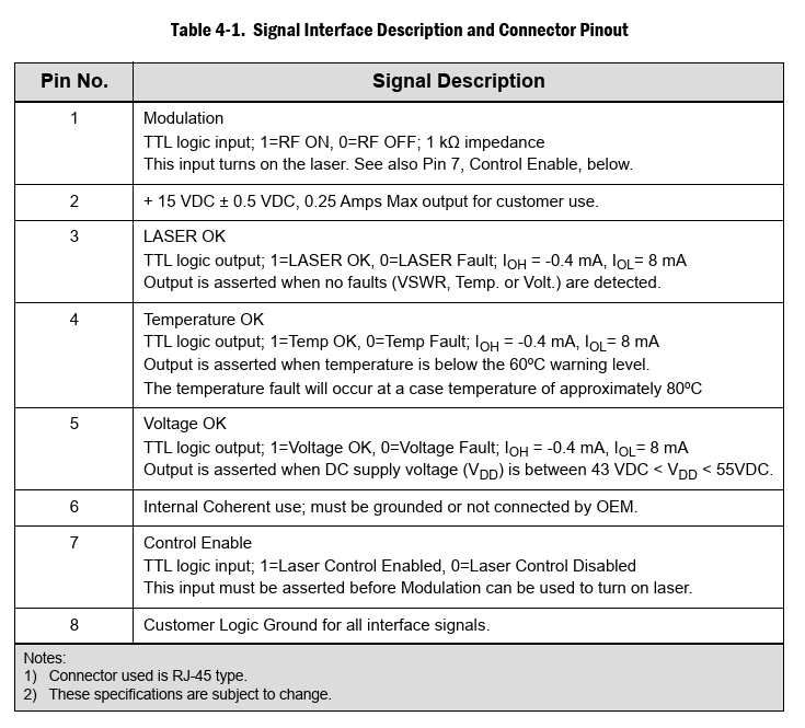
For anyone else looking for this information like I was, the answer is that the Epilog laser sources that use an RJ45 connector use the same pinouts as the Coherent Gem series lasers:
1 Modulation TTL logic input; 1=RF ON, 0=RF OFF; 1kΩ impedance This input turns on the laser. See also Pin7, Control Enable, below.
2 +15 VDC ±0.5 VDC,0.25 Amps Max output for customer use.
3 LASER OK TTL logic output; 1=LASER OK, 0=LASER Fault; IOH = -0.4mA, IOL= 8mA Output is asserted when no faults (VSWR, Temp. or Volt.) are detected.
4 Temperature OK TTL logic output; 1=Temp OK, 0=Temp Fault; IOH = -0.4mA, IOL= 8mA Output is asserted when temperature is below the 60ºC warning level. The temperature fault will occur at a case temperature of approximately 80ºC
5 Voltage OK TTL logic output; 1=Voltage OK, 0=Voltage Fault; IOH = -0.4mA, IOL= 8mA Output is asserted when DC supply voltage (VDD) is between 43VDC<VDD<55VDC.
6 Internal Coherent use; must be grounded or not connected by OEM.
7 Control Enable TTL logic input; 1=Laser Control Enabled, 0=Laser Control Disabled This input must be asserted before Modulation can be used to turn on laser.
8 Customer Logic Ground for all interface signals.
Please check this matches your laser source before trying anything! I hope this saves someone spending ages trying to find this information, tested with my 40 Zing laser source and works perfectly.
Be careful, it works only with the old series but the logic output for status is different.
It will not work with the new sources for edge maker pro series.
You can see the different between Epilog and Coherent, the epilog sources have led´s for status. Coherent have no led´s. The pcb´s from the logic controller are different.
Thank you for the heads-up—I’m glad you pointed out those potential gotchas, as safety is paramount here. That said, I do believe I did warn folks in my original post to proceed with care, and check that this matches their specific setup. On the other points, though, I respectfully disagree based on my hands-on experience. The Epilog laser source in my setup does support status output that aligns directly with the Coherent pinout, which corresponds to the internal status LEDs. It also provides 15V DC on pin 2, and all other pins match the Coherent spec as well. I took the time to meticulously verify every connection before swapping in a Coherent GEM tube into my Epilog Zing—double-measuring voltages, continuity, and signals to avoid any mishaps. To back this up, I reached out to a specialist shop that rebuilds and re-gases laser tubes. They confirmed my observations and noted that they use the exact same RJ45 test lead for Epilog sources as they do for Coherent-interfaced ones. I’m sharing all this in the spirit of helping the community troubleshoot safely—please take it as a starting point only. If you’re tinkering, make sure you fully understand the risks (electrical, thermal, and otherwise), have the right tools for testing, and consider consulting a pro if in doubt. Let’s keep everyone’s CPUs (and lasers) alive!