Feature Request: per-cut focus touch off for plasma cutting w/THC

reference post: Plasma cutting working

The above referenced post does a nice work sorting out the plasma cutter use case for LB. I’m in the process now of building a CNC plasma cutter, I expect to be ready to burn in about 2 weeks. I currently use LB on another router/laser CNC machine, and I like LB in many ways that I see will be beneficial and efficient when controlling and cutting on the new plasma machine. The system I’m building recommends CAD/CAM such as Fusion360 w/UGS, and I’ll use that just as I do now when routing on my current CNC when engineering drawings are required for the cut. But for artsie/craftie laser work, I like LB; quick and easy. So I’d like to request that LB consider what may be a simple feature to fully enable plasma use case when torch height control (THC) is available in the CNC plasma machine.

What I believe is lacking from LB right now, for the plasma cutter w/THC use case, is the “per-cut focus touch-off” (PCFTO) feature that Oz mentions in his reply to above ref. post. I will be using the Proma THC SD. https://www.proma-elektronika.com/compact-thc-sd-step-dir-pid-generator/ , which as the post describes manages the torch height once cutting has commenced, independent from gcode gen and send sw such as LB. As such, getting the initial torch height (ITH) set BEFORE EACH CUT (M3 command), and performing a Z retract AFTER EACH CUT (M5) is all that should be needed to round out LB support of plasma cutting. So I believe it may be relatively easy for LB to implement the missing PCFTO, by adding a similar feature as you recently did in “Device Settings -> GCode” window, which adds user defined gcode blocks to the beginning and end of cut jobs. For plasma support, simply do the same for begin and end of cut sequences within a job ! , basically prior to each M3 and after each M5 command. LB would also have to push/pop from an internal stack the last known settings of F, S, G21 or 20, and G91 or 90 as those will likely be changed in the user def code blocks. User def code blocks in this use case are something like this:

**** begin user defined gcode BEFORE each cut in 1 plasma job ****
(LB push F, S, G21 or 20 mode, and G91 or 90 mode)
G21 G91 (metric and relative)
(before start of job, user should move Z to set torch height no more than travel in next line, so less than 35mm above in my example here. Thereafter the Z retract in the AFTER code block will manage this for each subsequent cut.)
G38.2 Z -35 (-THT) F400 (THT=Torch Holder Travel, fast probe down until THT limit switch closes, connected to probe input)
G1 Z 6 (+THT) (fast retract to prepare for a slow probe down)
G38.2 Z -8 (-THT) F100 (slow probe down)
G1 Z 1.5 (+THT) F200 (retract to ITH or pierce height)
(LB pop F, S, G21 or 20 mode, and G91 or 90 mode)
**** end user defined gcode BEFORE cut *************************************

M3…
LB movements to next cut…
M5

**** begin user defined gcode AFTER each cut in 1 plasma job ****
(LB push F, S, G21 or 20 mode, and G91 or 90 mode)
G21 G91
G1 Z 33 F800 (fast retract to safe height and to ready for probe in next cut. THT not a factor here, torch holder is already fully extended in travel)
(LB pop F, S, G21 or 20 mode, and G91 or 90 mode)


LB move to next cut…
repeat.

THT is going to be different for each user’s machine, but otherwise its a constant the user will know. The units, relative vs. abs, retract height, probe start heights, ITH, and feed rate are whatever a user feels comfortable with in the user def code; even doing a double (fast/slow) probe vs. single probe is up to each user.

Bonus Feature: If the user def code blocks UI can be included as a Cut Layer setting, that would facilitate cuts on different types of metal as well as different thicknesses of metal and as such can be saved in the library. Also, consider that if THT can be externalize from the code block and set in the Device Settings, then it can be referenced as a variable in the user defined code block.

LB thoughts on this ?
Thanks much.

My machines: Mill Right CNC, Carve King Router/Laser, and Mega V Plasma/Router (in build)


Laser: Jtech 2.8W
grbl 1.1 on Arduino controller
Windows 8.1 and 10 for LB platform

Lou Cipriano

Is the torch height control GCode you’re using here relatively universal, or is this only going to be for this specific machine setup? I know you said each machine would be custom, but I mean are the actual commands (G32.2) going to be the same, and just the distances and feeds different? If the structure will be basically the same it would be easier to just have a “torch height control” addendum for plasma materials that included the heights and rates.

We’re going to have to have a profile type in LightBurn for things like plasma, vinyl, & water jet use where raster operations are removed, images are ignored (or only allowed on tool layers), and from there we can start doing customized device profiles for different machines. We’re also going to need a much more flexible GCode generator.

Adding pre / post cut move GCode would be workable for your case, but it would actually be easier if I know in advance that it’s for a plasma tool and you’ll be managing the Z. Otherwise, I’d have to parse the moves you emit and evaluate them internally so I know the states of everything (which might not be a bad thing to do anyway).

Oz, Great questions and suggestions. But first some clarification. A means for Torch Height Control (THC) is not what I’m suggesting. You understood THC correctly in BenM’s post from Nov, that I reference. THC as I know it always involves a hardware implementation, and usually is “bolt on” in an isolated way from the CNC controller, but I can certainly envision a CNC controller with included THC. In my case I’m using the Proma THC SD unit which is bolt on and isolated from the CNC controller other than it takes over the Z axis motor at the motor driver input, the gcode CPU doesn’t know its there. So yeah, Z moves and CNC controller has no clue where it is. but keep reading…

What I’m suggesting to add to LB, and I like your name for it in BenM’s post, “per-cut focus touch off” (PCFTO), is gcode programmable means to perform PCFTO, which the Z axis/torch performs for the purpose of precisely positioning the torch at the right height to make the pierce which begins the cut. This positioning is referred to as Initial Torch Height (ITH) or sometimes Pierce Height. There are mechanical/hardware means to perform this operation also, but it’s becoming much more common to have the gcode do it via the probe command (G38.2), since the positioning is a fixed height that the user sets based on power settings, material type, and thickness, since the torch is not moving laterally, and its common for CNC machines to have a probe input.

detail diversion necessary here: the probe command is not tripped by electrical continuity between the torch and the cut surface, rather its tripped by a micro switch on the torch mount which has a mini unpowered sliding Z axis build into it. So the mini sliding Z has a precise vertical slide distance/movement, gravity fed, 10mm or so, every machine is different, that is the Torch Height Travel (THT) that I reference in my code example. So it works by the normal and powered Z axis softly “crashing” the torch onto the cut surface and then it continues down, the cut material pushing the torch up the mini unpowered Z slider built into the torch mount, until the whole Z axis, the combined axes, makes the micro switch which is wired to the probe input. So the subsequent retract move is the sum of the THT + the desired ITH. Doing 2 probes is best, the first one faster than the second, and the first one coming down from a higher and safe retract height that would have been set after the last cut and prior to the XYmove to the new cut position, while the second probe move is from a much lower retract of the first, and going much slower so as to make THT as accurate as possible. But some people like just 1 probe move to set ITH.

To summarize: THT varies by machine; ITH varies by plasma amperage, material type, and material thickness; number of probe passes (moves) as in 1 vs. 2, varies by user or perhaps dictated by mechanical design of the torch mount; probe speed -Z varies by probe pass as in fast vs. slow and perhaps design of torch mount; max probe distance (the arg for G38.2 Z) varies by probe pass and depends on the previous retract height; and finally safe retract height for XY moves cut to cut varies by user, possible cut obstructions/collision points per job, and max Z travel.

re. parsing the gcode blocks if implementing the user defined per cut code blocks - parsing for Z travel is not reliable since the hardware THC bolt on gadget controls Z in an isolated takeover of the Z axis motor, so even the CNC controller doesn’t know where the heck Z position is after a cut. !:open_mouth: So the hope is that THC didn’t drastically move Z, they are just mm’s or tenth’s of mm movements to account for normal metal warp-age due to heat, in fact I believe there is a THC programmable setting to limit max Z movement +/- once it takes command. So the morale of the operation is, work/cut low in Z axis, retract moderately but a safe distance after a cut, pray for a non-collision XY move, and then pray for subsequent successful probe during the next PCFTO :slight_smile:

I like your suggestion for checking a box that it’s a plasma cut operation, let’s you disable things not relevant and monitor etc as you suggest. But I’m really thinking user defined code blocks before and after a cut is the way to go, it covers all machine cases and user preferences; and storing the code blocks in a cut layer setting seems practical from a UI and use case perspective.

I’m not sure I exactly answered your questions, but I hope I’ve clarified the hardware and necessary operations.
See this video for a very good example of a 2 stage per cut touch off and post cut retract sequence. The video is not my system, not even my machine brand, but its a great example, and it shows a potential collision at the 2:02 mark that the operator has to reach in and handle. Crossfire PRO - Cutting HMI Panels - FineCut - Hypertherm 85 in 4K - YouTube

So in summary, LB has all the right stuff for plasma except the PCFTO! LB has controls for lead in/out, delay, kerf offset, cut direction, material lib, cut layer concept to group cut settings, and if a collision occurs, the “run from here”/Start Here feature, which btw the PCFTO operation will need to be invoked when cutting resumes.

I’m still a few days to a week away from completing my CNC plasma build, so I’m fine if you’d like to table this until I run some trials by post processing LB gen’d gcode and running it. What I’ve described here is what I’ve learned, and what I have my hands on in terms of hardware, parts and instruction, not what I’ve practiced yet. If someone else would like to jump in on this discussion and offer advice, I’m all for it. BenM where are you ? You seemed to have a good perspective, description, and practical and successful use with LB and plasma as is.

Thanks for considering this or a similar feature.

The actual commands will depend on the CNC controller used on the Plasma Cutting table. In my case I have a Mach3 USB controller that uses G31 to accomplish the probing. Fundamentally the steps are similar, but the actual commands are different.

I’ve also added a 'poor man’s Ohmic sensor for Initial Height Sensing (IHS) that requires toggling M7/M9 before and after probing. So… yeah, the general purpose of the pre/post cut code is similar, but would be platform specific.

I should add, that I agree, especially for ‘artsy’ projects, LightBurn would be pretty much a complete CAD/CAM/CNC solution with your great Welded Text feature a huge benefit.

Uh, I might have gotten a little carried away with the CNC end of the solution. That’s probably a challenge. Also, direction of cut and kerf compensation might be another thing… :roll_eyes:

But we already have those. You can tell the direction of a cut by the direction that the animated selection pattern moves.

image

I didn’t know that, thanks for pointing it out. Having it done automatically (if it was an outside or inside cut) would be what we’re used to, but, it seems, you’re mostly there.
Is the setting cut layer specific or shape specific? Hint: The ‘correct’ answer is cut layer specific. That way inside shapes can be isolated to particular layers.

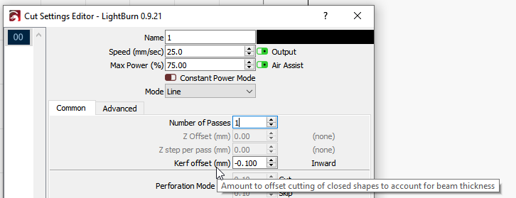
Kerf offset is cut layer specific. So yes, grouping cuts for kerf outward (left), inward (right), and centerline if so desired on clockwise rotation cuts will be easy based on cut layer line color.

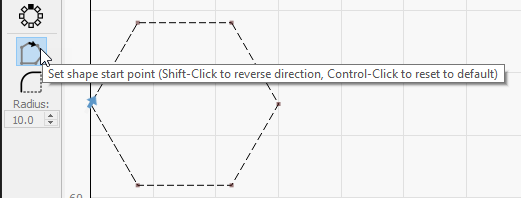
However cut direction is object specific, and you control it manually, by object, using the feature Oz pointed out, “Start Point Editor”. The online doc explains it well. “Optimization” feature will also influence object cut direction based on factors and conditions you can disable while generating the gcode. I believe if you override start point or direction via the editor, then it remains overridden even if optimization settings are enabled. I’ve used Start Point Editor a few times on laser jobs out of curiosity and found it pretty easy and efficient UI, but the arrow color differences between blue and grey are tough to distinguish for my old eyes :slight_smile: I did not have to mess with default optimization settings, and I noticed most if not all were enabled.

(launch the online doc from LB while running, it’s searchable that way, or use the pdf version. The Doc link at the top of this forum is html, so only the active article is searchable.)

1 Like

One more design element comes to mind as consideration is given to a PCFTO feature coupled with a Plasma mode which may disable certain illogical features like raster fill.

The Perforation, Tabs, Bridges feature is awesome for laser and would be likewise for plasma, so I’d like to see it enabled for plasma mode, for similar reasons perhaps (to keep cut shapes bound to the larger base material structure) but also for some new use cases, such as:

  1. artsy effect where only the kerf is thru cut in lines and graphic features so close they would otherwise dangle, break, or bend if the weeding/scrap area dropped out.
  2. metal brake/bending relief. For instance, I can brake bend 3 ft. of 11ga mild steel with a long perforated cut line just as easy as I can brake bend 18ga that is solid. After the bend, I can easily weld closed the perforations. So controlling my perforations, tabs, or bridges by location, quantity, and length is a fabrication advantage when brake bending thicker or alloy metals.

Net: PCFTO, if implemented, should be applied to every M3/M5 combination as if it were laser, including perforations, tabs, and bridge feature already in LB, IMHO.

This topic was automatically closed 30 days after the last reply. New replies are no longer allowed.