Feeling Lost but still excited (Laser Newb Omtech Polar 40W)

Hi everyone! I’m Morrigan, really new to the laser scene so bear with me and any of my silly questions or poor lack of laser lingo. I’m a quick study but I’m struggling a little bit and I’m hoping all you gurus out there can help me out in this journey into laser cutting and engraving!

To start, my boyfriend and I are huge into gaming and making our own stuff. We have 3D printers (both FDM and SLA). We make our own stickers. Painting miniatures… the whole shebang. Its a passion of ours.

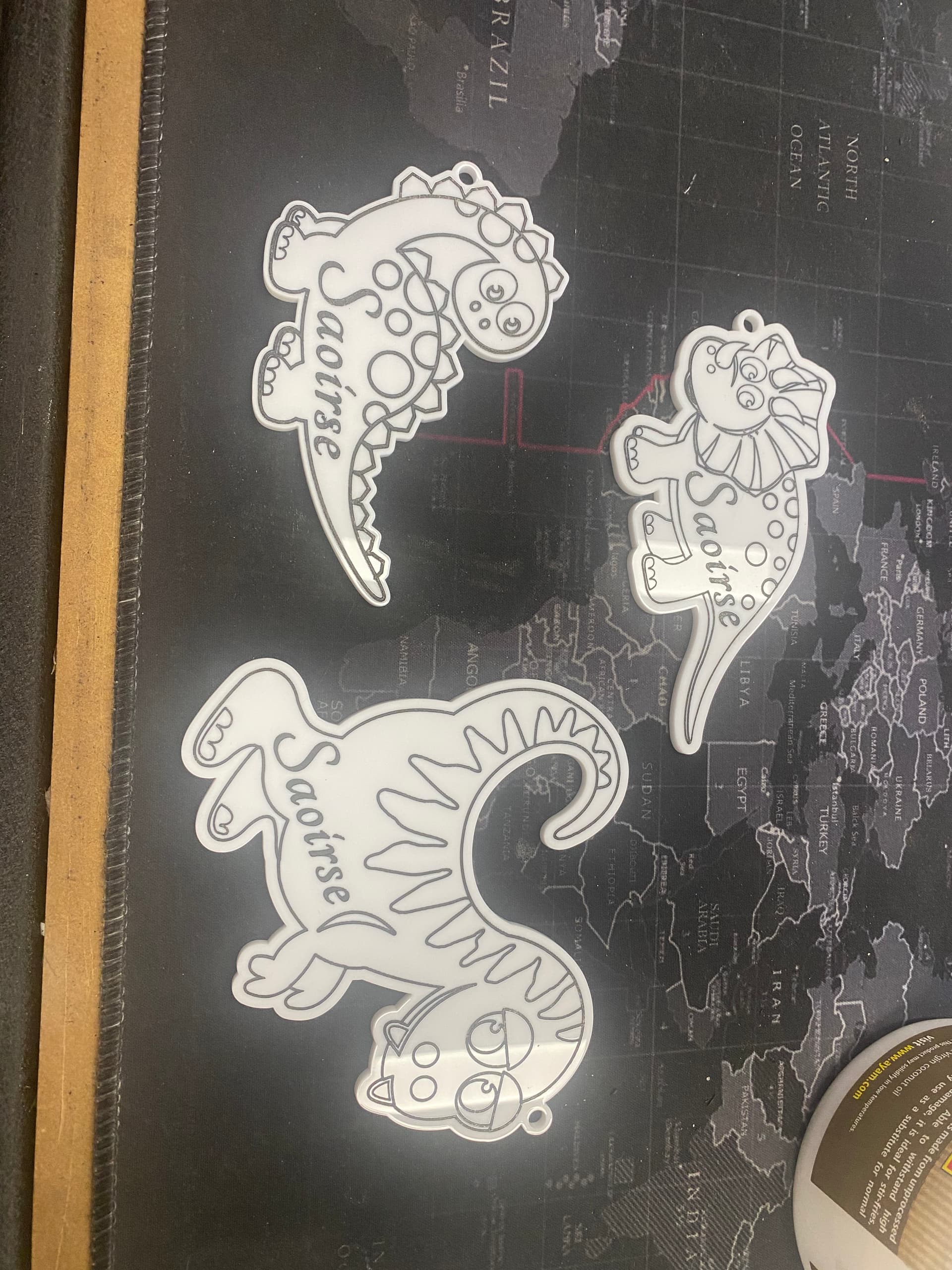
Well! We finally took the plunge into engraving as we genuinely wanted to start making our own game tokens, especially for games that we enjoy that don’t have them out there on the internet already. That’s what has me here and what I’m reaching out about.

So far my journey as been a little frustrating and a bit of a struggle. I will relay my struggles and some things that I have already found a resolution for.

Type of Laser that I have:
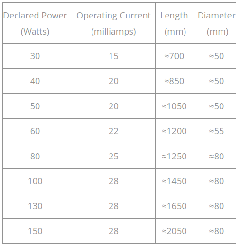
Omtech Polar 40W No upgrades to lenses or mirrors, no console

So far with all of my testing (and I’m unsure if this is normal or if I should be identifying a problem or anything). We tried on wood first but being that we want to work with acrylic that is what I’ll be talking about.

  • The lowest power setting that will affect materials is 16. This is for anything. And this is even barely a light grazing. With this testing we determined 17-18 is where we see actual MA’s on the reader inside of the rig.
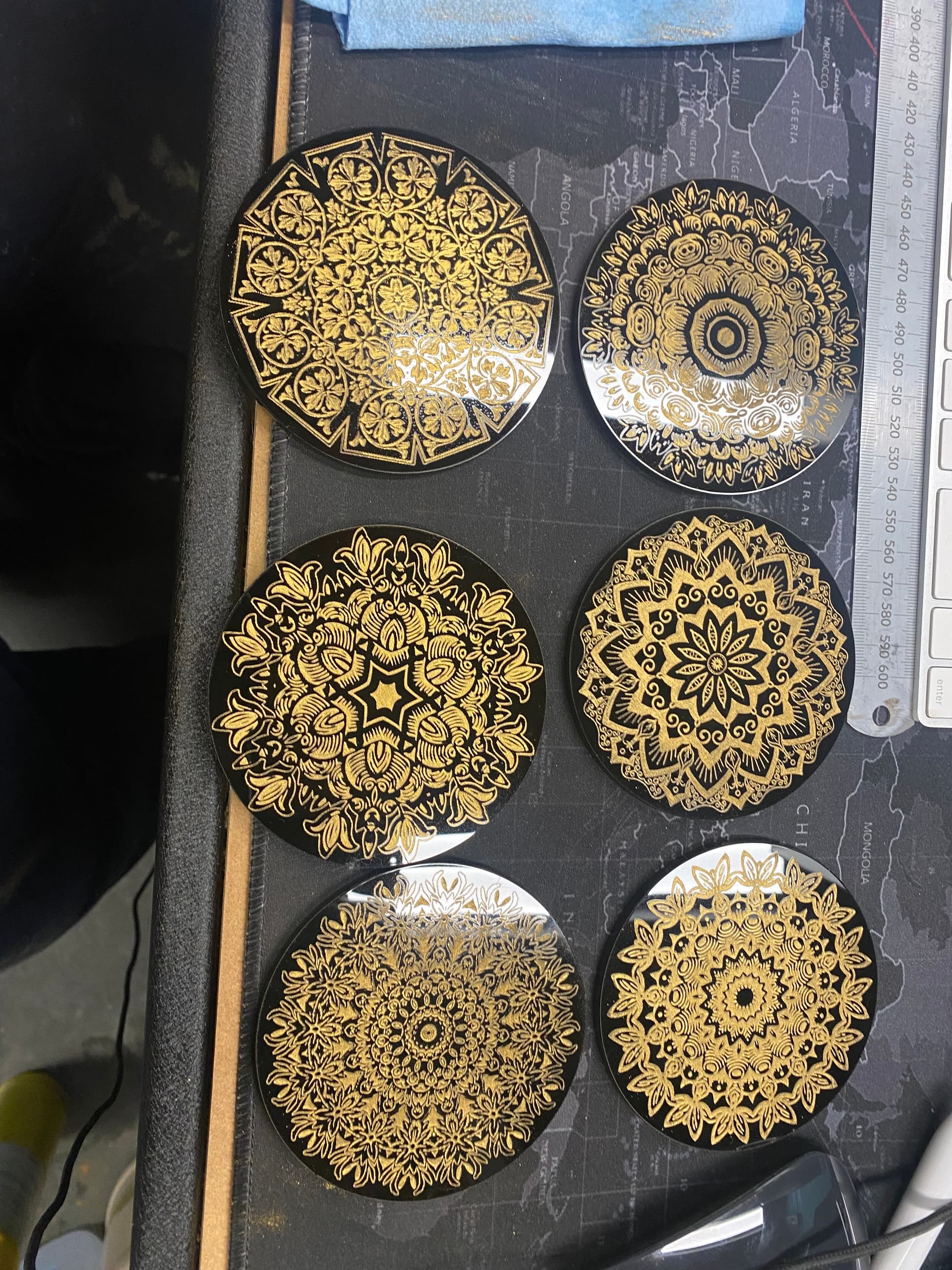
  • LPI doesn’t seem to have a huge effect on engraving. We are getting what I would consider extreme grooved lines in our acrylic.
    Tested speeds and powers have had a range of settings but these are a few that we have stuck closer to per settings found in videos and testing:
    • 150MM/s 18-20 power 300LPI (I have done 1 pass, 2 passes and 3 passes)
    • 100MM/s 18-20 power 300LPI (I have done 1 pass, 2 passes and 3 passes)
    • 500MM/s 50 power 400LPI (Omtech recommended settings per a document they sent us)
      500MM/s 50power 400LPI (1 pass) with a 100MM/s 20max/15min offset spiral fill (1 pass) and a 500MM/s 50 400LPI final pass (I’ll be honest, so far this is the one that I find to have the few/least ridges.
      Note: Per Omtech support I cannot use “crosshatch” in Lightburn. No reason was just flat told don’t do it.
  • Cutting is smooth and beautiful, it is gorgeous once we figured out that leaving on tape is key to keep things from fogging (or burning the acrylic back in).
  • Should there be an absurd amount of dust left behind when engraving? No matter what setting (air assist or not) it seems like the engraved portions are covered in a latent dust (this is whether there is tape or not). We have taken to using a toothbrush and water to clean it out but it just seems like there shouldn’t be that much when it should be blowing it all off.

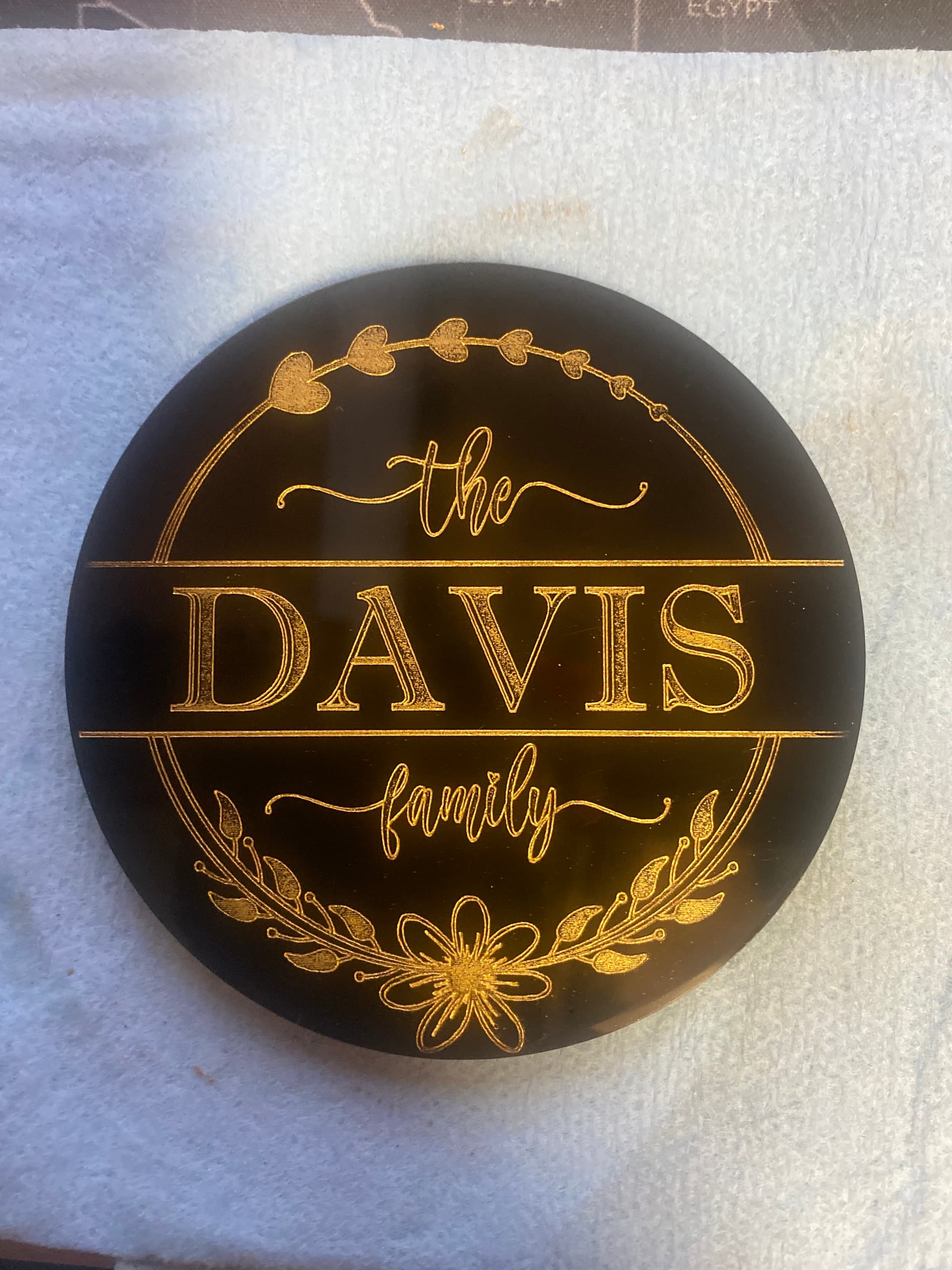
Getting the ridges to be less pronounced is huge as it currently affects the overall final quality and finishing for the token so any help would be appreciated to get me in the better/right direction.

Next, I was curious what methods some people use to color fill areas? I’m looking for an effective way that isn’t super time consuming to color them and cover those ridges. I have been looking but haven’t found a lot of suggestions except to use acrylic ink or paint which I have been trying but I feel like I’m not quite getting the smooth appearing results that I see in some.

Its fabulous to meet you all. I look forward to being a contributor as I learn more and thanks for the help in advance!

Hi Morrigan,
congratulations on the new laser!
let’s start with the easy stuff first. I use wax paints like Rub & Buff to fill the engravings and coconut oil for cleanup. After I get it like I want it I rub on a few coats of carnauba wax.


When you engrave you want to keep the line interval low. The ridges you are getting is most likely due to lapping over of lines. Start out at about 150 lines per inch and drop the number of lines about 20 lines per test and see if you get an improvement. Another thing to try is increasing your focal distance about 1/32nd of an inch. moving the laser head out of focus causes the material surface at the bottom of the cut to melt a little bit and smooth out. It’s all trial & error though, you have to work out what works best for your machine.
Good luck and hope you have heaps of fun.
Cheers,
Rob.

Hello,
Some pictures would help us assist troubleshoot.
The LPI needs to be ran per material and a nunber decided upon that looks best for you. The height of the lens from the material has a huge affect on the look, as the width of the beam changes the closer and further away you get from the material.

I suggest running a focus test, and an interval test as a start to zero in on an adequate height from material as an operational baseline. These tests shouod be ran per material if youre gonna be manufacturing at any sort of scale.

It happens that you and I have the same laser, though different name… same machine and same factory. My distance settings for engraving is 7.5mm with a 3mm acrylic material. My LPI is set to .18 for acrylic, it frosts perfectly with hardly any noticeable ridges at all. I engrave at 25min 30max power at a speed of 150mm/s. The dust is very normal. Just brush it off with a toothbrush. For coloring it really depends on the design and number of colors, but using masking materials on a sheet of acrylic is a good start…I would need more info before suggesting a solution. After engraving and cut out you brush dust off, leave masking material on and then paint a single color over it…let it dry a bit then peel masking off. Its also good to reverse the text so you see the details through the acrylic, its much cleaner than looking at the tooled side.

DPI/LPI is number of lines (I use dots) per inch. If you have 1 dpi, then there will be one scan per inch.

Normally we talk interval, an interval of 0.10mm equates to 254 dpi. A 1.0mm interval is 25.4 dpi. 1 scan line every mm adds up to 25.4 dpi.

Understanding and using a proper interval is very critical… Although this Laser Everything video is on Photo Engraving and done using a fiber, it is great for explaining how interval works and how to pick the right interval for any type laser or material… Definitely worth the time to watch…

Good luck

:smile_cat:

Firstly, I will get pictures at my next test currently all of my tests are painted to see if the paint will cover the ridges.

So this is something I see a lot of without a lot of “how tos”. Or more accurately a lot of the videos I’ve watched assume I know how to do these and have already done them. (IE they say things like “you’ve already run tests and know the settings”).

It makes me feel like I was expected to be a laser guru before I even started to learn.

However, with a quick google search it looks like lighburn has a test for these specifically that I was not aware of. When I run this test, what sort of results should I be looking for? And increasing the distance, will that reduce some of the finer line details?

@jkwilborn Thanks for the video I will check it out.

@Rob_H I was actually going to start testing crayons so that is a great suggestion! Thank you!

This should answer your interval questions. I’m confident of that.


Maybe you just don’t realize it … yet :crazy_face:


If you bought a metal milling machine, you’d have a spindle, a tool bit with a certain diameter and a fixed number of flutes. The metal would be of a known type or maybe an alloy. With a calculator or an machinists handbook you can look up the speed/feed for that material and bit configuration.


Now examine your laser… The tube is manufactured and each is different as far as the actual beam and how it’s composed. An important part is how closely the mirrors are aligned. It should be relatively close to specifications, but it will vary.

Still referring to your tube … how much power does it have? My 50W China Blue had about 43 - 44W. It was only 880mm in length. How long a tube is relates to power as the amplification occurs within the tube between the mirrors.

I’ve used this table for a number of years, along with a Mahoney power meter and it seems real close.

Notice my 50W tube was 880mm, so it was more like a 40 - 45W tube. You can’t convince me OMTech didn’t know this …

We then take this beam and bounce if off a few mirrors… each mirror taking it’s slice of power… The beam increases in size as it traverses it’s path to the head and down the lens tube.

Lens… what is the focal length of your lens? I have four lenses, each produces a different spot size and has a different waist or focal depth of field. Many machines have different distances it must travel and the spot size is inversely related to the beam size. Larger beam coming into the lens, the smaller the possible spot size…

Most of the time the material is natural, so each piece will have a different enough makeup… Even rocks of the same type vary …

In short everything here varies… absolute numbers can’t be had, even ball park values can be flaky.

Many of the manufacturers post ball park figures… use at your own risk… you need to start somewhere

I don’t know how you deal with these without adding a console.

Before I do any work, I take a piece of scrap and check it with a line. Cut though if I’m going to cut or just engrave to ensure it’s doing what I want. I do this through the console, I can change speeds and power very easily from the console. I keep changing the values until I get the cut I want. Usually these are pretty close, but I always test on scrap before burning up a $10 or more piece of acrylic. Most of the time these don’t really require a change, but I do it to save material…

Don’t feel left out, we all have these issues…

Good luck - have fun

:smile_cat:

Each machine for manufacturing has a minimal knowledge set to operate, so this is why youre running into this assumption. Lasers come from the industrial sector so there are less walk thrus and more requirements to figure it out via empirical research because everything is unique.

The focus test is a test that sets the laser to its highest point, and burns a line. It then moves the laser head down (or Z table away) and fires another line. It does this until the test parameters are finished. You will notice the one far away is a big thick line because the laser is ‘defocused’ and the beam hitting the material is wider. As you ramp the laser head down, you will find the sweet spot where the laser is leaving a very thin line perfect for detail work. You then select the best looking one. Each line burnt will have a tag next to it with a number value, associated with a Z height. This distance is how far from material the laser head is. This is your focal distance optimal setting.

Plug this value into your Z value to set the lens where it should be.

The interval test assumes you have your correct focal distance, because the results you get are a direct result of how far the laser is away. Meaning if you change your focap distance, your interval setting may change due to how wide the laser is when it hits your material.

When you run the interval test, you set a range of LPI/Interval values to test. I run 10 at a time, and select the best looking one for whatever I am doing. I start at 0.10 and go to 0.25 the machine then fills in squares of a set size at the various intervals.


Some have very visible ridges, whereas others are super smooth. You then choose whatever look you want, and this value is entered into your LPI setting on the fill layer, and your squares end up looking like that all the time.

Keep in mind if you put in a thicker material to burn the distance between the burn surface and the lens change so you would need to maintain the focus test optimal distance by modifying Z values.

So to recap a tiny bit the focus test determines the optimal distance of the laser lens to be above a material for the desired line or beam width.

The interval test runs a set of various LPI fill settings so you may visually select which setting is optimal for the desired outcome on a specific material.