Fill+Line Alignment Issue

I have been digging through the forums, and have seen some similar issues with a range of solutions, but overall do not seem to be working well for me.

I have gone through the alignment drill with 50x50mm boxes at 250mm/s, 100mm/s, 50mm/s and 25mm/s. At 250mm/s my lines are skewed about 5mm. Relative to the outline the line appear to start late and finish late. I have entered the skew values into the device settings and I am getting pretty close.

If I turn off bidirectional, the fill lines are all lined up correctly but the outline box is still offset.

What I really want to know is what is causing this? Can I get to the root of the problem and fix it without having to have the skew values set. As stated, I am getting close to the correct values there but they are not 100% spot on yet.

Lightburn 0.9.19
RUIDA 6445G
StepperOnline Stepper Motors NEMA 17 59Ncm
StepperOnline Drivers DM542T
RECI 87.1W Laser
1200x600 Bed

I have also tried rotating the fill angle 90 degrees. At 300mm/s it was off by 4mm instead of 5 with no correction turned on.

All other settings are default out of the box with the exception of setting calibration where you put an offset in for distance (in the RUIDA controller). ie you have the machine draw a 100mm line, measure it and put the actual value in. All lines are coming out the correct dimensions.

I have also tried the boxes in RDWorks and get the exact same results.

What more can I provide?

Here are my settings.

I would be confirming thereā€™s no mechanical issue, before diving into firmware settings.

250mm/s isnā€™t really fast, for a large machine, although you do have lightweight steppers.

Make sure thereā€™s no play at all, before you go changing backlash.

There is a little tiny bit of play on the X axis (typical v-rail slop), so I rotated the engraving to the Y axis (Linear Rail) where there is no play at all.

I have triple checked everything mechanical, everything is tight. When I do simple squares they come out perfect, right size, everything lined up as expected. It is really just the fill at this point that is giving me heartache.

The long axis uses a pair of the NEMA 17s.

Would making changes to the steps/rev on the driver impact this? Would a better quality power supply have any impact?

belts shouldnā€™t be tight. loosen them off, grab the pinion in your hand and pull it so thereā€™s no play at the top - it doesnā€™t have to be ā€˜boingā€™ tight :slight_smile: One finger.

The shoulders of the pinion and belt carry all the load, so it just needs to be tight enough that the belt doesnā€™t slide outwards and skip, and on lightweight machines, itā€™s reasonably easy to torque something a half mm out of alignment and the belt starts to rub against either rim and then to skip or vibrate.

If youā€™re going to do a lot of work on your machine, it pays to go through it entirely and check torque, parallelism, angle. I have a digital woodworking angle thatā€™s perfect for checking. And while youre doing that, check electrical across the machine, especially grounding.

Thanks Bo. I may take a little tension off the belts. I originally had them lightly tensioned now they are boing tight.

Machine is a brand new build, and I have been going through everything over and over. The results I am getting are extremely consistent, just off. As I said I can correct this in software just wanting to know what I can correct in hardware so that it works without a fudge factor.

Without backlash settings the scan is starting late and ending late. Lines are exact length they are supposed to be.

This image is at 250mm/s on a piece of Trolase.

laser

Thatā€™s a hell of a backlash for 250mm/s

Check pinion grub screw tightness

Also, do a hatch test, so you check in both axes.

I get the same on both axes.

I am 99% sure at this point it isnā€™t mechanical play. I have tightened and retightened everything.

I am thinking either the power supply is just slow to react, or I have something set wrong in the controller.

The same on both axes is a good indication it isnā€™t mechanical.

Thatā€™s a lot, at 250mm.

What controller, what laser?

One method to check is to set your origin, draw a 25mm square at slow speed (~50mm/s), then ā€˜infillā€™ it with a crosshatch exactly 25x25 at high speed - 250-300mm/s - do a single direction scan and see if it is starting all one side or the other from the square dimensions, then do the same with bidirectional turned on.

If itā€™s consistently all to one side or the other of the square with unidirectional scan, itā€™s most likely timing. If the bidirectional ā€˜straddlesā€™ the square, turn about - so l>r is 2.5mm to the right of the square boundary, r>l is to the left - itā€™s timing, if it starts dead on the square boundary, itā€™s probably mechanical.

Does that make sense?

Without a datum of the square, you can only see the lines relative to themselves, not the origin. By putting the square as a datum, you can reference it in all directions against your origin.

If you get identical results in X and Y, then you can pretty. much discount mechanical, unless the machine is really wobbly :slight_smile:

Bo, I really appreciate your time and thoughts on this.

What you are saying makes sense. Given what you are presenting here it is a timing issue and not mechanical. On fill, the line starts inside the bounding box and ends outside. The laser is starting late and finishing late in both directions. If I one direction then all lines are the same and all lines start inside the box and extend outside. The extent that they start inside is the same length that they extend outside.

Lightburn 0.9.19
RUIDA 6445G
StepperOnline Stepper Motors NEMA 17 59Ncm
StepperOnline Drivers DM542T
RECI W1 87.1W Laser
1200x600 Bed
Cloudray Power Supply DY13 100W

I have entered backlash settings into Lightburn and that corrects for it just fine and everything seems to be working as expected. I just want to know what I need to correct to keep from having to have such large backlash settings as I know they will probably jump up and bite me at some point.

Electronic ā€˜backlashā€™ can usually be traced back to a less-than stellar component. Thereā€™s really no problem putting any number into backlash compensation, except you will be reducing your maximum bed size by the compensation x 2.

All itā€™s doing is telling the controller to fire Xmm before the start, to get up to power at the right time and place.

But, most problems with backlash are mechanical. 2.5mm in each direction, like you are seeing is very unusual.

Compensation is usually in the region of 0.05mm-0.2mm.

Lasers fire fast. They hit their required voltage in tiny fractions of a second.

I think you have a mechanical issue, still. That may not be mechanical backlash - there may be no slop at all - but it may be a stepper/driver issue.

So, everything is tight enough, but the acceleration is too high, for example, and results in not hitting its mark at the right time in space.

These are my settings for X and the laser firing. Compare with yours.

Screen Shot 2020-12-21 at 1.26.34 PM Screen Shot 2020-12-21 at 1.27.18 PM

Thanks Bo. It will be a couple of days, but I will get over to the shop. I think my acceleration is quite a bit lower then what you are showing here.

I will run through a range of values and post back my response.

Max Acceleration is just that - itā€™s a global cap (with the exception of the E-stop value). The other acceleration values are set in the cutting and engraving sections, and will generally be lower. If you verify that the delay is electronic, the ā€˜Scanning Offset Adjustmentā€™ table (called Reverse Interval in RDWorks) will be the way to fix it.

Bo referred to it as backlash, which it is, but there are distinct settings for cutting backlash in the controller, which are for mechanical slop, not firing delay, so I just wanted to make sure you didnā€™t mix up the two.

And heā€™s right - 5mm of shift at 250 mm/sec is very high. If it was a stepper driver issue, Iā€™d expect to see the laser fire early, not late - the motors would be ā€œbehindā€ the laser firing. If the high-voltage power supply is slow to respond, youā€™ll see the laser fire late. Bo has likely forgotten more about this than I currently know, so youā€™re in good hands.

Thanks Oz.

The adjustments I made were to the Scanning Offset Adjust table. Overall everything seems to be spot on. I made a control panel out of acrylic for the front of my machine and everything was sized, positioned and cut perfectly. Circles are nice and round. It is just the fill that seems to be off for me and for the moment that is fixed with the Scanning Offset Adjust table.

1 Like

If itā€™s working , itā€™s working, however, you are masking the problem, rather than solving it.

When you get a chance to look at the actual values in the controller, they will be helpful.

Iā€™ve been looking back at notes, and trying to remember from ā€˜badā€™ machines, but I cant recall seeing a 5% offset error, so a bit lost, right now, at a solution.

My normal process would be:

Get the cnc components working spot on - steps/mm, power (to steppers - enough current at the right voltage), belt/shaft the correct tension/grub screws snug, check for clean y-axis shaft and x-axis rail, clean and lube if necessary, all electrical and electronic components properly grounded - just an FYI, the cause of most intermittent issues is poor grounding - the chassis properly grounded through the earth pin on the power cable, not the ground pin on the back of the unit.

But, yours isnā€™t intermittent, itā€™s repeatable, which leads to the next step - check controller config against a known-good config.

After that, itā€™s the laser PSU and tube - physical integration, especially the HT line from the PSU to the laser anode (great mnemonic - Donā€™t PANIC - Positive is Anode, Negative is Cathode) and a solid ground from the cathode to the chassis. Thereā€™s very little you can do with laser timing - it goes from pre-ignition to ignition in milliseconds. The most obvious areas to look at are the connections and the power-supply itself. Usually when itā€™s breaking down, you get power when you donā€™t want it, rather than it being slow to ramp up.

And 'slow is relative: Doing some back-of-the-fag-packet calculations, 200mm/s is covering 2.5mm in 0.0125 seconds, so one-and-a-quarter hundredths of a second. Paltry for a device with a 20,000Hz switching interval - 0.00005 of a second.

As itā€™s consistent, and cutting is working fine, I would discount (at least for now) a power supply issue. If you have or can get hold of a laser power meter, you can confirm that the power supply is in spec.

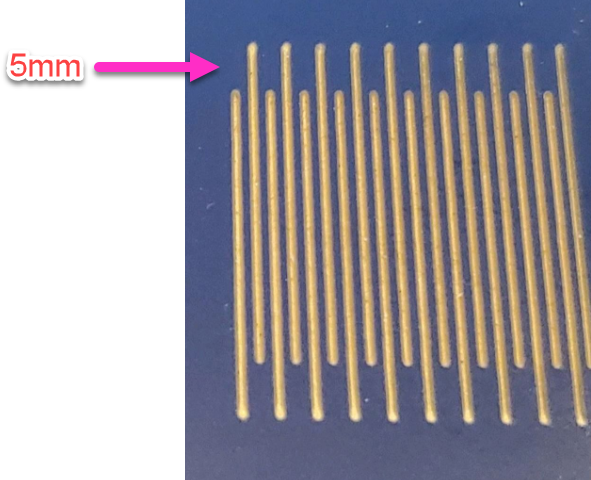
So, scanning vs cutting problems, in my experience, are always mechanical in nature. You may not see it, because all the object points are offset in the same direction. Itā€™s as obvious as bulldog balls with a bidirectional scan.

The way to prove that is to:

  • set your origin
  • hit ā€˜pulseā€™ to set a datum point at origin
  • move the head to machine home (not origin)
  • then start a fast (>300mm/s - ideally at the highest speed your machine can handle) repeating job that has itā€™s first cut at the origin - so a square is ideal as the corner should be right at origin

  • Let the job finish and then hit ā€˜pulseā€™ again.

You should only have a single point from the pulse. If you have two, or the start of the job is offset from the origin point (thereā€™s a divergence from the start of the square from the pulse point) you have a mechanical issue.

Further pulse points can be used to refine - so:
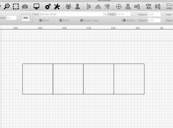
  • Set LBā€™s ā€˜Moveā€™ panel speed really low - 50mm/20mm/sec.
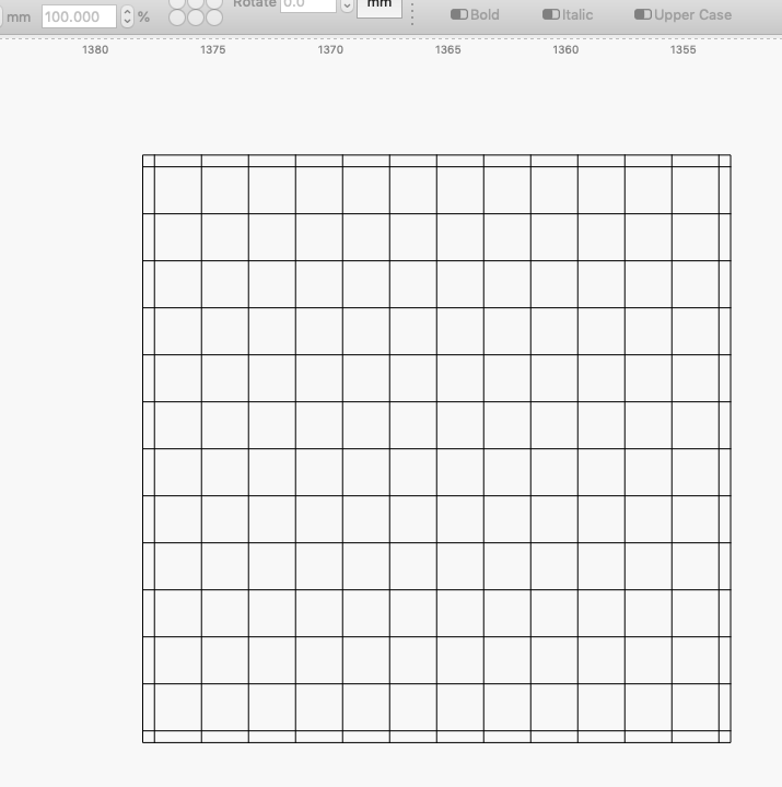
  • Create a job that replicates 4 100mm squares,
  • set origin
  • pulse
  • using the move panel, move the head +400mm in X
  • pulse again
  • move +100 in Y and pulse again
  • then move -400 in X and pulse again.

Only use the ā€˜moveā€™ panel, not the machine panel, as any movements there will a) have you hunting to move 400mm and b) moves at the machines framing speed.

You now have a matrix of 4 pulse dots that should mirror the corner extents of your 4 100x100 squares.

In LB ā€˜Laserā€™ panel settings, turn off ā€˜optimise cut pathā€™, make sure ā€˜use selection originā€™ is set, then move the head to 0,0 and send the job. (The reason I move the head to machine zero is so it has to move to get to the origin before the job starts/ The reason to turn off optimisation is that you want all four squares to cut, not have collinear lines missed through optimisation).

Check the output - you shouldnā€™t see the pulse dots as separate from the line - the line should run through the middle of the dots. anything other than perfect alignment of the lines and pulse dots indicates a mechanical issue.

This topic was automatically closed 30 days after the last reply. New replies are no longer allowed.