Find center on a Galvo Laser machine & focal lenght

I guess, the title of this thread is self-explaining: how can I find (and align) the center on my Bodor Galvo laser machine?

Some informations on this issue: my workspace on the machine is 310x310mm large and the (formal) center is located at 155x155mm. But in fact, the (real) center has a slight offset to this (formal) center in X- and Y-direction, which I can only estimate (approx. 1mm in X-direction and approx. 0,5-0,8mm in Y-direction)
In fact, althought the offset seems to be low, this has an impact on engraving circular graphics. Especially, when this grafics/letters are small in height and the plane to be lasered is narrow.

On the machine, I have a red laser pointer, which obviously marks the center of the galvo laser on the workspace. Here I can detect the offset.

Another point is the focal lenght, which (obviously) has an impact on the roundness of the laser graphic. As written above, I often engrave circular grafics which are round in shape. I think, this is trivial, but the graphic on the part seems to have a deviation from the round shape and tend to get elliptical.
This problem is particularly evident and visually recognizable with graphics that are engraved on narrow surfaces. How can I ensure, that the round grafic (in Lightburn software) is applied fully round on the part? Which settings to I have to manipulate to solve this issue?

The machine defaults to the center… The offset is usually described in the field in the device settings…

Who setup your lens?

:smile_cat:

This is a problem on my machine: how can I setup the lens? I do not know, if the manufacturer did this job, but I didn’t. Because I do not know, how.

Take a look at these videos I found them very useful

You have to import the EZCad2 configuration file into the setup of Lightburn… This is the markcfg7 for my machine. You are prompted to do this when you setup devices in Lightburn… did you?

This is where it’s requested when you create a new fiber type device or edit an existing one.

image

This is the path on the usb stick

/LMA22A1095JZ/Ezcad2.14.16/plug/markcfg7

I would think you should have one for each lens that the manufacturer shipped with the machine. Each lens is unique, irrelevant of focal length.


The videos posted by @Mooseuk are very good… The EZCad2 Corfile2 software is by far quicker and easier than the manual method. The EZCad2 stuff only runs (somewhat) on Windows.

Sing out if you need help or have questions …

:smile_cat:

Done so. My filename is markcfg0. I also have a *.cor file, which is imported in the settings.
I have imported this file but there are still troubles that occur:

  1. I have drawn a rectangle (120x120mm) and lasered this. But, the output has a dimension of 132,5x133,5mm (X/Y). Galvo 2 is my X-axis. In fact, the scale factor is almost 10% too large, but I can’t overwrite this manually in the settings, because both fields are frozen.
  2. All 4 lines of the rectangle are not exactly straight, but (slightly) bended. Horizontal lines (in X-direction) are both concav while the vertical lines (Y-direction) are convex. Same here, I can’t

My lens specifications: F-Theta Lens, f=420mm, Lambda = 1064nm

What else can I do?

I was advised to use markcfg7 of the 8 of them that came with the machine.

There was no cor file that came with mine, and I was advised to import the EZCad2 file, the markcfg7 and not use a core file with it as the markcfg7 has all the lens correction data.

I have to ignore the numbers, as I’ve run into a cor file that wasn’t right and all my measurements are off. I beat my head against the wall trying to figure it out… it was configuration…

There is no use serviceable parts, like the gantry laser, that I’m aware of you can check…

IMHO, you have some kind of configuration issue…

I think the only thing you can do is ensure there isn’t an issue with the file you selected, maybe the markcfg should have been 7 not 0?

I also don’t know what happens if you import the file (markcfg) when you create a device for the lens, then also apply another lens file correction (cor) file.

In my 40 years of computers, most of the problems are configuration issues…

Do you have markcfg through markcfg7?

:smile_cat:

No, I do not have markcfg7 or 8 file.

Anyway, I have calibrated now all parameters manually and it works.

For example: a rectangle of 120x120mm in lightburn software is now 120x120mm on the laser print.

I also corrected skew and trapezoid and the offset from red dot pointer to center of laser.

There isn’t much on these that user fixable at least hardware wise… it usually boils down the the proper configuration…

Sounds like you have it licked…

Have fun…

:smile_cat:

Unfortunenatly another problem occurs, when I change the z-value (height) of the lens. Dimensions are not scaled properly any more.
For example I engraved a part, which is 25mm in height - I adjusted the lens by 25mm and checked this on the ruler. The center of the lens deviate the the result became unuseable.

I have tried (as written above) to calibrate the machine manually and on the advertised focal lenght (= 488mm) I had proper results as in the YT-videos shown.
But, althought the focal length remain the same in fact (distance lens-engraving surface) the laser graphic deviates.

I don’t understand how this could possibly be… The lens or glavo is changing heights which is common, but the image isn’t consistant…?

If the focus point is the focus point how could anything change…?

The machine doesn’t know you’ve changed where the head is on the Z axes…

My 300x300mm lens is an F420, so it’s focal length is apparently shorted than yours…

I don’t know what to tell you, I can’t imagine how this could occur…

Maybe someone else has some clue…

:smile_cat:

Right! And this drives me crazy, because I do not know, where to start searching for the reason. In the upcoming weekend I will post some pictures here to illustrate this issue.

When I look at the engraving result, it seems, the a) the center point of the lens deviates out of calibrated one and b) the shape of the letters changes.
In detail, I laser engraved some circular orientated graphics/letters and a circle must be round (otherwise it isn’t one). But, the circle became ellipitical, when changing the height, although the focal length remain the same: e.g. a part with height 20mm, I turn the lens up by 20mm (20mm shown on the ruler of the machine). Then I measured the distance between lens and laser engraving surface of the item, and focal length remains constant by 488mm.

Post some photos, maybe it will be a lead we can follow…

:smile_cat:

Here they comes.
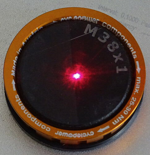
To figure out this issue with some detail pictures. I’ll start with the (bad) result, which can be illustrated on a circular laser engraving particulary well.


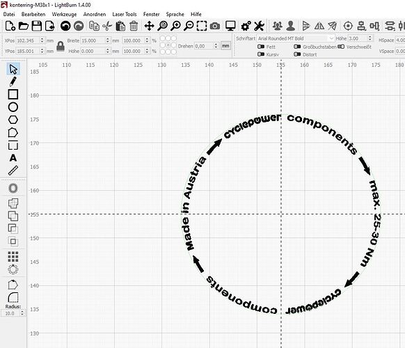
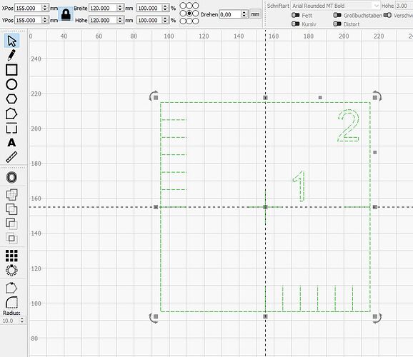
In lightburn software this looks like this:

As you can see on the green, dashed circle, the graphic is round.

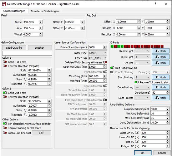
To come to my setup on the Galvo machine and in lightburn software:


The field has offset values in Y-direction by 1mm and the red dot in X and Y direction, both 1mm. However, when you look at the result (1st picture above), the deviation of center seems to be far beyond 1mm of the offset value.
As described in aboves forum posts, my problem is, that when I align round graphics on Z = 0mm, these offset values are correct. Only, when Z-value ≠ 0mm (and this is most commonly the fact) circular graphics got a shape as in my “result”-picture illustrated.


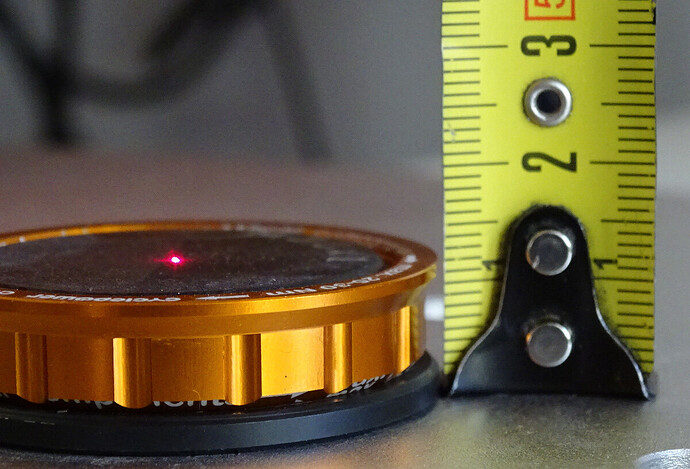
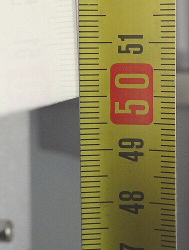
A plate on the machine shows a focal length of 488mm, plus the height of the device and (orange) ring

So, we have in total 488+12mm = 500mm. This value I measured out as it it show in the figure of focal length (bottom to beam, measured on the bottom of the beam).

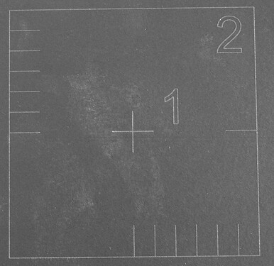
I did calibration to the machine as in YT-videos shown, which this graphic. The picture below shows the result


and this image illustrates the template in lightburn. Shortly sumed up: it’s a rectangle with 120mm lenght on each side and all lenghts in the picture above correspond to the template in lightburn. I mean, 120mm are measured 120mm in laser etched graphic. Lines are straight. All values of scale, skew, Aufweitung and Trapezoid, shown in the preferences, were empirically tested out by lasering the rectangle with numbers etc., controlling the result, adjusting the values and so on to find proper result.
As you can see in the image above, the result of calibration correspond (almost, beside a deviation caused by taking the picture) with the template in lightburn software.

But, finally, cicular graphics deviate strongly in position: they are eccentricly aligned, not full round (circular shape, as the graphic in lightburn is)

I hope, these images illustrate my problem and I hope to get an answer, how to solve this issue.

Have you checked that the laser head is square? if it is tilted in relation to the Z axis slide, you will observe that changing the lens height will also move the laser from side to side, so if your engraving is good on the laser bed, if you change the Z position and keep the part to be engraved in the centre of the bed you will notice the offset shown in your picture

As you can see in my pictures above, the calibration square correspond to the calibration template. All 4 lines of the square have a 90° angle to each other. I have proven this even with a ruler.
Or do you mean something else? Please clarify then.

I mean this angle… is the laser beam square to the table?

1 Like

Sure, it is.

This topic was automatically closed 30 days after the last reply. New replies are no longer allowed.