Flite Test PDF plans cutting -- help?

Okay, so I want to use the plans from Flite Test to make some models using foam board. I have done some experimenting and I am able to cut black foam board using my 5W diode laser. I am in the process of destroying more samples to do a material test on the black foamboard to see how to do the various bits and pieces. I’m getting a 10W diode laser operational, and I hope that I will be able to cut white foamboard with it. (Never even tried the 5W laser, every source I read says that it’s not great at it.)

I’m running into some problems.

  1. The Flite Test plans do not seem to import cleanly into LightBurn. Some of the details just aren’t there at all, some images show up as a black square, some text isn’t there at all, either. Not really a big deal, I don’t really want most of that anyway, but it would be nice to have the option. Is there a way to get more complete information imported into LightBurn?

  2. There are many different types of lines that need to be there. These are generally denoted by colour, and it seems the LightBurn almost gets this by putting them as different layers, but some things aren’t separated by layer, and I can’t see why. In this case, black lines are cuts, red lines are 50% score, green and cyan lines should just be surface marks. From the material test, I should be able to do all of these different kinds of cuts. I suppose that I need to be better able to manage the layers function. I admit that I’m not particularly good at this yet. Again, is there a way to maybe automate this a little?

  3. The coloured lines are represented by dashed lines (so that they could be still discernable in a black and white print-out.) I will want these cut out. I can add a line in the appropriate layer, but it still seems to keep the original dashed line as well, and I’m afraid that these will end up in an additional pass. A double pass on what should be a 50% score will be a problem. (Hmmm. I suppose that what I could do is use the line draw on a new, unused layer, and turn off the output on the existing layers. The problem would be following curved lines…)

It just seemed to me to be far too convenient to just use the laser instead of going through the trouble of printing the plans and trying to transfer them over from printer paper to the foam board. Much more efficient to just get the laser to do as much of the job as possible. I suppose “last resort” might be to just get it to just at least mark the paper on the white foam board…

Anyway, if someone has some advise to share, I’d love the help!

1 Like

What format are the plans in?

I assume this is with black core foam board but please confirm.

This most likely won’t work. White foam from my experience is almost impervious to the blue diode light. Give it a shot, however and let us know how you carry on.

Can you link the specific model that you’re attempting to import? I’ll test to see what types of artifacts you’re talking about.

Can you post a screenshot showing the discrepancies you’re referring to?

Automate what specifically?

I assume this means the dashed lines are hard-coded as disconnected line segments. Depending on how these are designed there may be various techniques for recovering the intended lines.

Ideally you’d be able to do the whole thing on the laser. No sense going back and forth if not required.

Thanks for the replies.

As of now, the 5W laser is no longer a concern. (It just caught fire. – I was right there and no other serious damage, but that 5W laser is done.) I started a bit slow on the material test seeing if I could cut balsa, and it cut the balsa, and set the diffuser I had under the balsa sheet on fire. By the time flames were visible, it was too late for the laser module, as well as much of the machine it was connected to.

They are downloaded as a .PDF document. (As mentioned in the title, lol.)

Correct. Black paper, black foam core. Cuts nicely.

Well, if I can even mark it effectively, that’s a start, and I won’t have to worry too much about transferring the drawings from paper to the foam. I’d heard that it wasn’t easy, and never even attempted it with the 5W module…

Pages 6, 7, and 8 are the relevant sheets.

There is another version at

which is only 2 sheets for the same plane, however this one requires a larger sheet than the foam sheets I buy. I suppose it doesn’t matter if I move parts around and nest them myself. The second version is less complete, but I don’t really need the information printed on the foam board, so long as I can identify the parts.

Basically saying "All BLACK lines go to layer 1, all RED lines go to layer 2, BLUE lines to layer 3, CYAN to layer 4, etc. Like I said, it seems to mostly do this

Probably. It would depend on how the lines were defined to the PDF distiller, I guess. The second set of plans seems to have these as solid lines. Harder to tell if you get it printed on paper in black and white…

Well, this project might be sidelined until I get my new laser built. I do have the one 10W ready on the CNC, so I will give the white foam board a try. (It’s $1.25 CAD/sheet as opposed to $2 for the black, which is part of the reason that I want to use it. Also, black lines on black paper for “score here” lines aren’t as easy to see.

Cutting white paper in general is surprisingly difficult with a diode laser but still very much possible. From what I recall of when I attempted this I was able to burn through the paper outside of the board with a little fuss but got stuck on the foam. I didn’t try engraving to it but it’s likely doable. Having said that, I’m not sure it would be a time savings over printing and gluing. Worth exploring I would think.

Sorry. I should have been more specific. I wasn’t sure if you were using the term loosely/generically so wanted confirmation.

There are certain features that can be generated in PDF that LightBurn do not currently import. For example text and patterns.

As a partial workaround, try first importing the PDF into Inkscape, then saving to SVG or copy/pasting into LightBurn. I’ve just tried this and much more information is preserved.

Can you call out specific areas where it doesn’t do this? Not obvious from the limited testing I’ve done.

This will be the easier design to adapt. You can use LightBurn’s perforation feature to accomplish this.

I’m noticing small gaps in cuts. Are these deliberate to act as tabs to hold down the parts? If so, the gaps are surprisingly large but I’ve not worked much with foam board.

I want to start by making sure that I say thanks for helping!

Hmmm. Looking through stuff this morning, it’s not as easy to spot. It does seem to be linked to some of the PDF issues. I may try a conversion to .DXF as well. I never trust the size units after a conversion to .SVG. (I’ve had trouble with CNC cuts from .SVG dimensions being weird.)

Actually, I think these are blunders. Not important if you’re transferring from printed paper, but problematic when trying to use the original digital files. The plans with the dashed lines seem to be better with this, but… of course they’re dashed lines.

Some of these are alignment marks and don’t need to be cut, only marked. For those, the dashed lines are just fine. It’s the ones that need a 50% score cut (Cut through the top paper, basically, but not cut through the bottom paper. I’m okay with that level.

What complicates things is that some of those are deliberately left. Some of the cuts are left incomplete to be finished after assembly, so that control surfaces don’t move until after you’ve glued things together.

So what it looks like is that there will be a lot of manual work involved in transferring these plans into something that can be computer cut. (Hard to complain when they provide the plans for free.) So I either put the work in up front to get computer cuttable plans, or put the work in with scissors, pen and x-acto knife to do the transfer work. The advantage to the first one is that it only needs to be done once, and once done, lets the CNC do what computers do best – repeat tasks, so a second model, if desired, becomes a lot less work, so… I’ll put the time in to make it work.

This is probably the way. At least there are scales on the documents, so I can check that the dimensions are correct. It will most likely end up being more accurate than if I printed them onto letter paper (and whatever error my printer produced) then tried to transfer the shapes with pins and pen (and whatever error I introduce there.)

Again, thanks!

I have the Tiny Trainer plans in dxf format and Lightburn files.
TT Fuselage.dxf (195.6 KB)
TT Fuselage.lbrn2 (73.8 KB)
TT wing.dxf (117.5 KB)
TT wing.lbrn2 (43.1 KB)

3 Likes

Wow! you have just saved me a ton of time. Thanks!

1 Like

You’re welcome.

I’ll revise that statement. Since the speedbuild kit that I bought for the Zero has these tabs in it, they apparently are hold-down tabs to be cut manually. This does make some sense since they package up and sell the kits, their CAD probably has them built in.

I made an error with my laser setup. I did not have the persistent setting for the cut power turned on, and LightBurn was expecting it, so every time there was a rapid move, the laser would turn on, but then whenever there was a direction change, the laser would turn off again. :poop: So I ruined my material. then I wrecked the rest of it trying to figure out what happened. Oh well, there goes $3. :wink: More important, of course is the time to go back to the dollar store to buy more.

Anyway, the waste part gives me lots of stuff to experiment with getting the best performance out of the laser.

I’ve learned a lot about how RepRap Firmware on the Duet board deals with the Gcode.

  1. G0 commands in laser mode are executed as expected, at the fastest travel speed that you have defined in the firmware. (I have mine at 12000 mm/min, so that’s pretty fast considering that it’s a CNC router primarily. Very happy that it does it!)

  2. Default power scale is from 0-255. I can’t find the setting in LB to change what it expects, it seems to be 0-1000. I remember that I changed it for my GRBL laser in LB, but in this case, it was a mostly trivial matter to change the setting in RRF, so I made it do that.

  3. Persistent mode for G1 commands is off by default. I did find where to change that in LB, but since it makes the files slightly smaller, I decided to turn on persistent mode in RRF instead.

  4. M8 is not supported. I get a bunch of “command not supported” piling up in my error queue. not sure what I turned on, or failed to turn off to get LB to stop generating the command. It’s not in the RRF dictionary. I have found some references to coolant in CNC mode in Marlin docs… Maybe air assist? That’s not under program control, so I guess I’ll hunt down wherever that might be turned on in LB and turn it off.

In terms of the machine… The laser mount on my CNC machine apparently flexes, so whenever there is a suddent change of direction, the laser shakes a bit, and the result is a squiggly line for the next few mm. Speeds of up to about 600mm/min seem to be OK, but above that, it’s really annoying, so I have some mechanical issues to deal with… Either that ot I need to seriously reconsider my acceleration settings. Maybe I’ll change it for now just in laser mode…

Native support for RRF would be nice in LB. I’ve read the argument that it’s not worth a lot of development time, and considering that some development seems ot have been done in RRF to support the lasers, and I think that I can get the bugs worked out in RRF to make it work with the Marlin support it’s OK, but some things like the air assist being a different command (Maybe allow substituting a fan on command to enable one of the on-board fan MOSFETs?) would be a nice option for the Marlin post-processor.

I have another laser on the drawing board, and it’s a toss-up. I have more Duet boards, which would mean RRF, and a small FluidNC/GRBL board, so it just depends on how many motor channels I end up using. If I end up with a Z or A axis, it will probably be the Duet, otherwise, the fluidNC/GRBL board will do the job, and I’ll most likely use that.

Max value for this is set with S Value Max in Edit->Device Settings. Just change that value to 255. But sounds like you changed this on the firmware side to 1000 so no need to double up.

What is persistent mode?

This is indeed used for air assist. You can stop issuing M8 if you disable Air in Cut Setting. However, I believe M9 commands are still sent in that case to turn off air assist.

Note that the next major version of LightBurn is set to have a customizable g-code generator where you may be able to tweak things to match your machine.

1 Like

so the default behaviour for RRF if it sees the following:

G0 X10 Y10 ; Go to X=10, Y=10 at the fastest possible travel speed with the laser off
G1 X110 S950 F1800 ; Travel to X=110, Y remains the same (at 10mm) set the laser to power 950 and feed rate to 1800mm/min
G1 Y110 ; Travel to Y=110, X remains the same (at 110mm) laser power sets to zero, feed rate remains the same (at 1800mm/min)

so with this, I get a laser burn at 95% (Now that I’ve fixed my scale) 100mm long parallel to the X axis, and only that.

Persistent mode means to treat the “S” factor the same way it treats X, Y Z and F. If not specified, keep it the same as the previous value. It’s probably a safety feature so that you don’t get the laser firing when you didn’t expressly command it to (I guess in case someone forgets an M5?) which is fine if you configure LB to always send the "S’ factor for every move. As is, I didn’t do that. I suppose that it wouldn’t hurt to do so, the extra filesize really isn’t an issue, but I think it is reasonable to trust LB to not forget to turn the laser off.

Anyway, it’s just a parameter that has to be specified in the start Gcode for the laser jobs.

I have ben using FliteTest plans for quite a while. My previous laser was old tech and ran off Windows XP. For that I had to use TurboCad to trace all the parts. That way all the different cuts can use a different colour… I the converted file to .plt and loaded into laser. Since now having an up to date machine I still use this method with no problems loading into Lightburn. The colours can then be changed to your choice.
Using this method the drawing loads at the correct size.

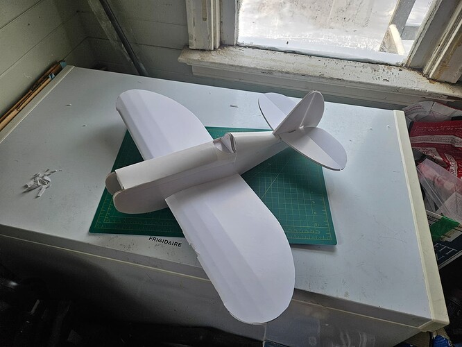
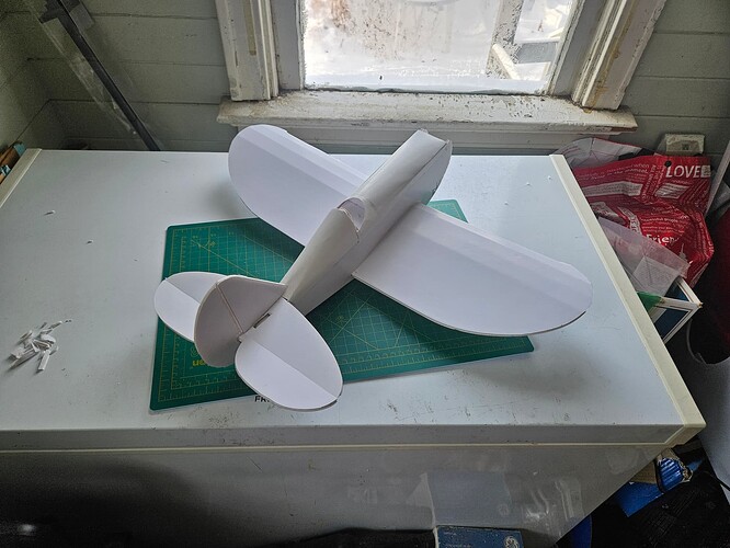
So in the end, I decided to try the mini Sportster instead of the tutor as a test run.


Well, it seems I was successful at cutting plans. I did a lot of editing, removing the indicators for bevel cuts, removing paper, etc. I left some of the part notes, running at high speed/low power to just leave a black mark on the paper. I had 3 kindmls of lines, cut, score and mark. Cut ran at 95% power, score was just barely enough to cut the paper surface (45%, I think) and mark ran at 12%, and higher speed. Of the 3 the cut was least satisfactory. As mentioned, white foam is not the easiest to cut with a diode laser.

This foamboard isn’t the right kind though, it has a glossy texture, and for parts where you are supposed to peel paper off, it doesn’t come easy. The leading edge of the wing broke when folding it, and some things just didn’t fit right, I had to widen a number of slots, including the wing holes, so I don’t think the wing chord is correct anymore. Also getting more than 50% of the way through this stuff wasn’t hapening and there was a lot of melt in the foam under the paper. (I get some of that with the black foamboard, but less melt, and more cutting.)

But this was a practice build.

I think I will cut the real one using black foamboard. I will need to run another material test.

1 Like

Nicely done.

Did you cut the foam using the 10W diode? I wouldn’t have thought that possible but would be pleased to know it’s possible.

No, the white foamboard wouldn’t cut in one pass with the 10W diode. I cut it about 50% of the way through at 90% power, 1200mm/min, but there was definitely some undercut where the foam melted instead of cut nicely, but it was really easy to finish the cuts with a razor knife.

The score cuts were lighter, just enough to cut the paper, and etch lines were enough to mark the paper,

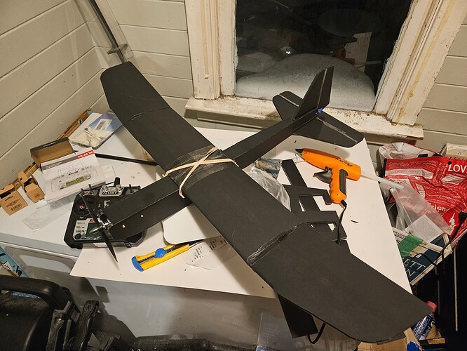
I’ll be trying one with black foamboard, which I know that I can cut with the laser easily enough

So the black foamboard cuts quite nicely at 80% power, 1400mm/minute, (still need to finish a few cuts here and there, but not bad at all) scores the top paper at 30%, 1400mm/min and makes pale marks on the paper at 7.5%

Edges are slightly undercut from melt, but not bad. 140pmm/min is kind of the motion limit on the machine right now, I can see the laser module wobble a bit if I go faster. At this the cuts are quite straight and clean.

I muffed up the tail, the control horns are on the wrong sides. Or I muffed up the fuselage, and the slit heights are reversed.

Well, I’ll crash the plane and have to replace stuff, pretty much guaranteed. I’ll fix it then. In the mean time, I’m going to fix my lightburn file and reverse the fuselage image, because then it’s just one group.

I 3D printed the conteol horns and firewall. I pulled the .DXF plans into Fusion, and extruded the outlines from the plans to create a 3D printable firewall and control horn, then printed them in PETg to a height of 1.6mm, which is pretty close to the thickness of the FT parts. I have a “sport wing” with ailerons cut, but not assembled. Gotta get used to flying again, and dont need extra complication.

A FT power pack A2 provides motor, servos and ESC. I need to double check the balance point, since I can’t see the mark inside the wing, lol.

2 Likes

Both planes look great Dan. Hopefully they fly great too! For a little larger plane the Simple Scout is a great plane that is easy to fly.

1 Like

This topic was automatically closed 30 days after the last reply. New replies are no longer allowed.