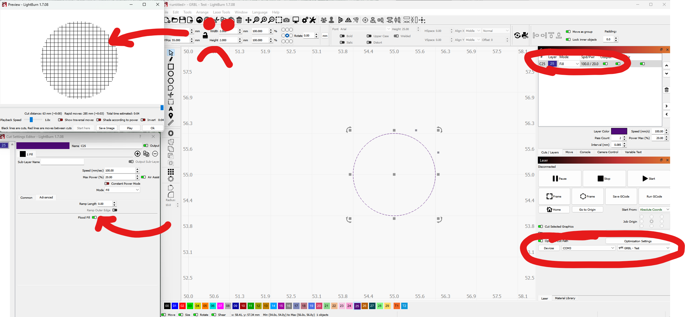
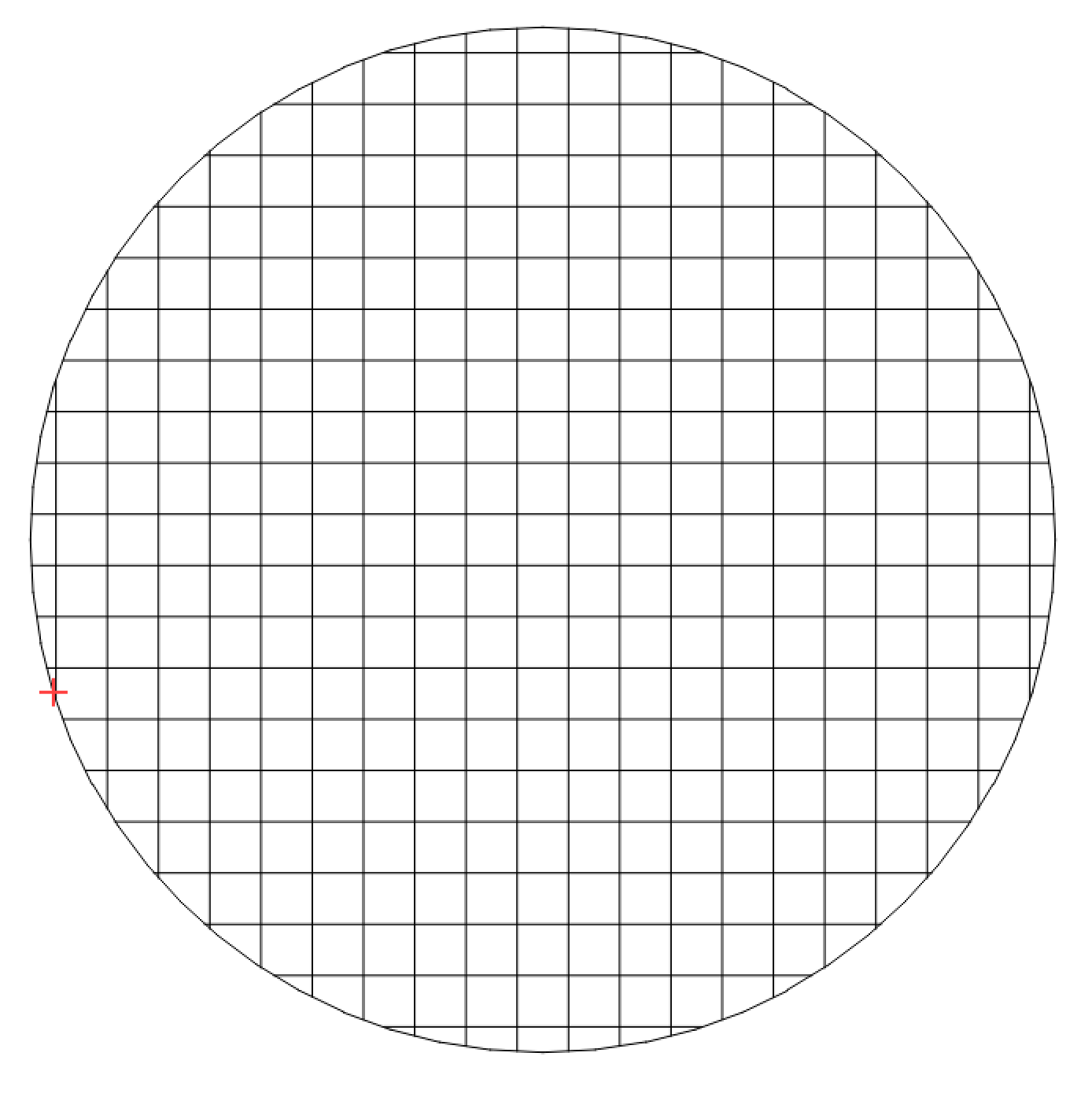
I’m using an xTool F1 Ultra which is GRBL based apparently and I have an extremely specific / niche application where I need flood fill to be active. However, it seems the ‘Flood Fill’ setting in the Advanced tab doesn’t change anything. The circle previewed below is just for reference to show the issue. What am I doing wrong?
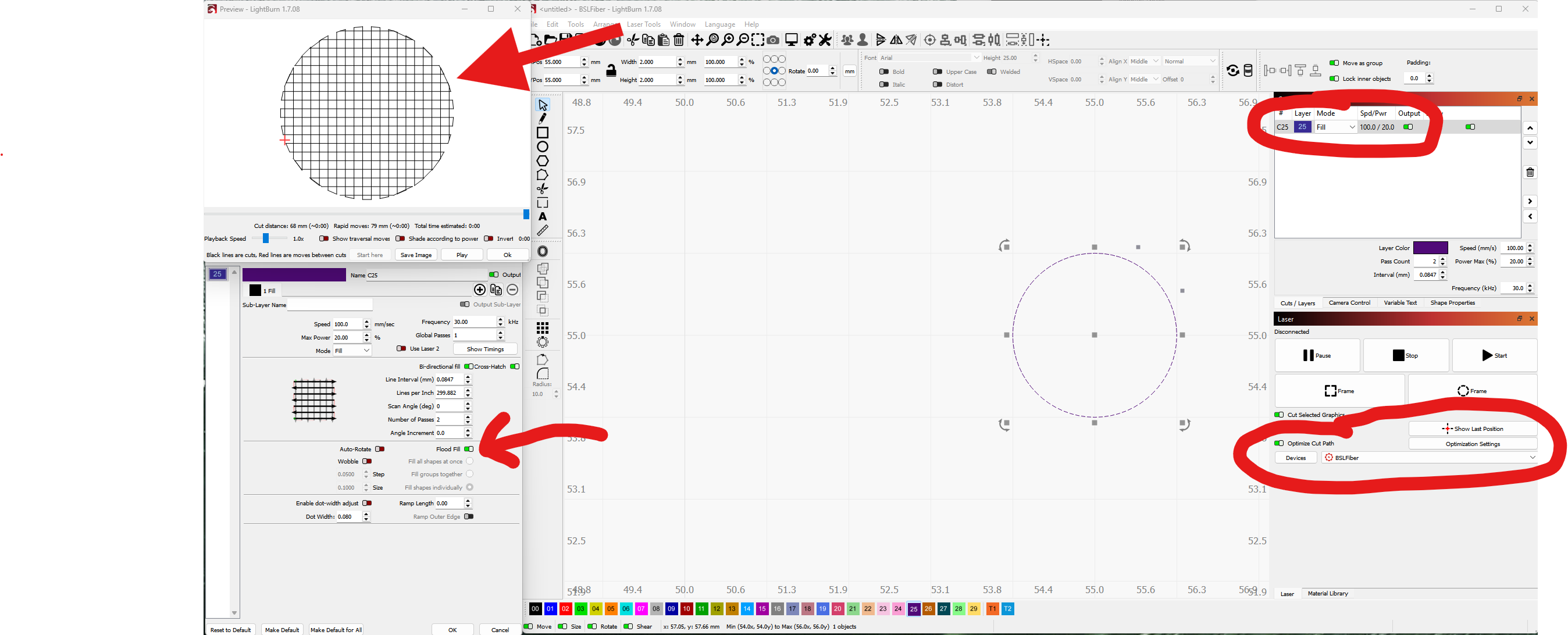
Preview and settings with flood fill enabled on BSL type laser, this is what I’m looking for:
Also there doesn’t seem to be an option to replicate the Angle Increment setting from the BSL menu and I also really need that. The F1 Ultra stock software comes with an ability to do this, is there somewhere I can set that up?
I think flood fill is really used for gantry machines. I think it’s for skipping blank areas.. Don’t use this on the fiber, so I don’t know what to expect.
It’s the type of shape you use. Flood fill does the same on all types of lasers, if you have a perfect circular shape, flood fill fills it just regularly. Are you looking for offset fill? This will follow the shape. Flood fill only fills the area with an optimal way, “flooding” it.
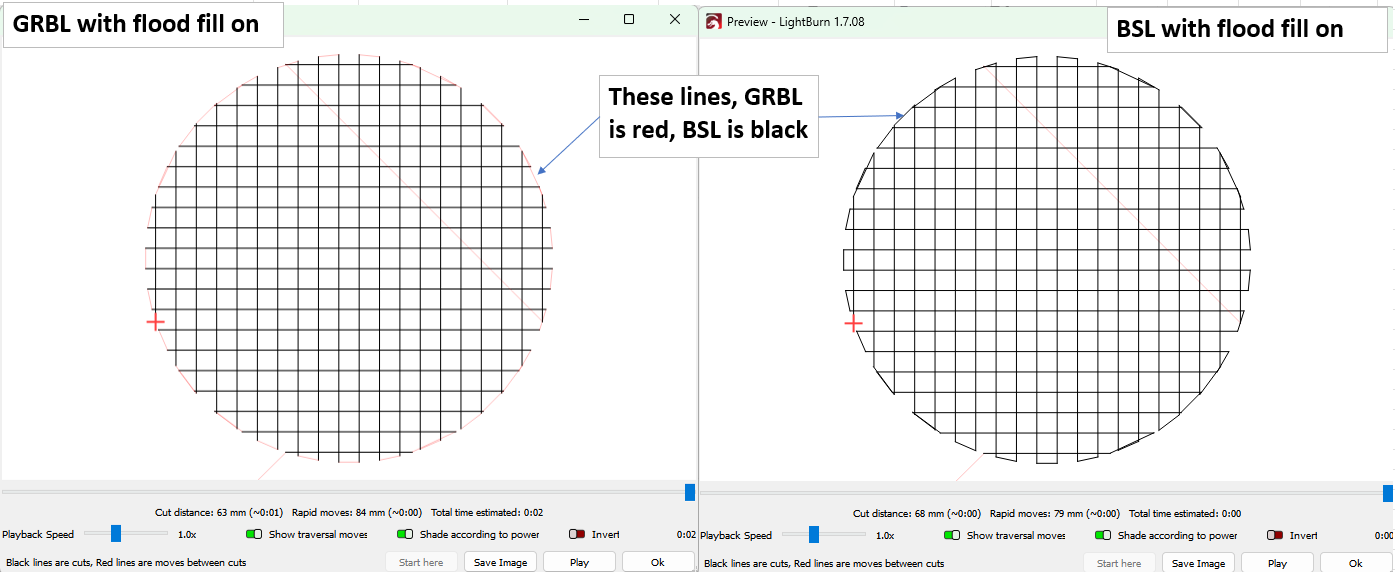
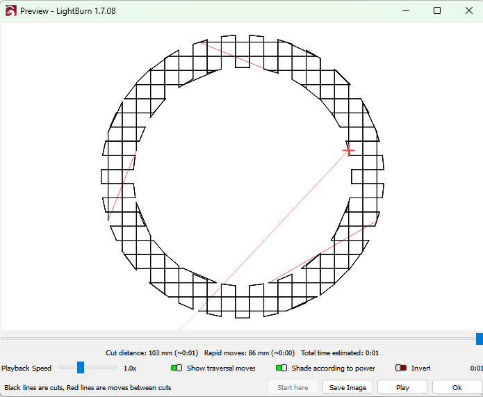
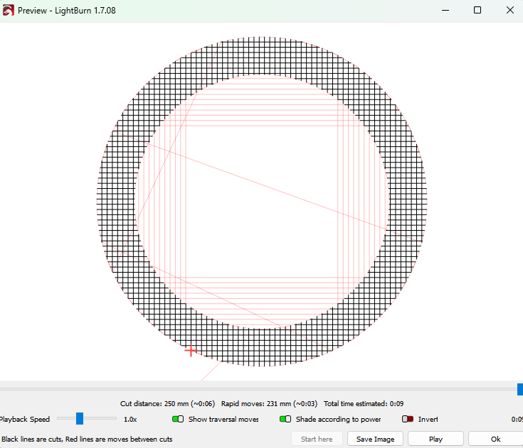
Thanks for the quick responses! It appears I wasn’t clear enough in my original question, my apologies. I understand the general intent of flood fill and know that a circle is not strictly relevant to the ‘flood filling’ part but it still demonstrates the issue. I attached a side by side picture of what the preview looks like for the BSL laser flood filled and the GRBL laser flood filled (showing traversal moves this time as well).
Basically for the GRBL laser path the laser has traversal moves (red in the preview) between scan lines and it doesn’t cut them whereas the BSL laser does cut them (they’re not traversal lines, they’re black). This may seem trivial but in my actual use case it’s more impactful and results in significantly cleaner cuts. Offset fill did not work in this case unfortunately and produced much rougher edges despite fiddling with it for a bit.
Also, any ideas on how to use the angle increment setting that is available for BSL lasers but doesn’t seem to have an equivalent setting for GRBL lasers?
I’m not versed in either the F1 or BSL machine, but what I see from the preview is it appears you are doing cross hatch. A regular flood fill would only have lines in one direction.
If you’re looking for a smooth perimeter, may I suggust adding a line after fill sublayer? That would send a pass of the perimiter after all your fill work is done leaving a smooth line. That would cover the portions missed by the BSL also.
The issue with sublayers is that they execute in serial so it doesn’t behave quite how I need it to when doing many passes (this takes ~1000 passes), I need the heat to be dissipated and spread out as much as possible on my teeny tiny parts to prevent melting the part but at the same time keeps it consistently hot enough to get a good cut. It’s an extremely tricky balance and the flood fill for the BSL lasers is the only way I’ve found to get a good result.
Flood fill does work with cross hatch though, it just basically does the flood filling twice orthogonally aligned.
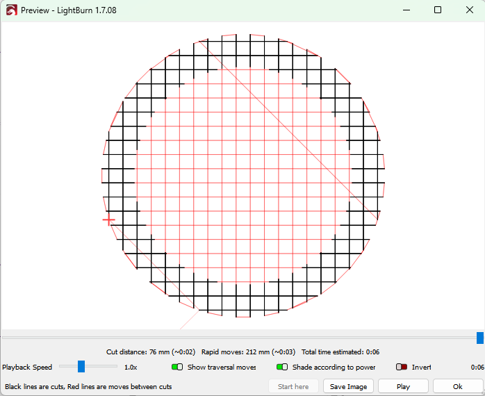
Looking at it more the flood fill just seems to behave very differently for the GRBL lasers, it doesn’t seem to try to avoid white space, see the preview pic below showing how the BSL laser flood fill does what you would expect but the GRBL one goes over the white space in the center.
BSL (no lines in the center of the ring being engraved)
Clever idea to manually do the crosshatch, hadn’t thought of that! Unfortunately it does the same exact thing though as the crosshatch. It seems to just simply not actually flood fill the area.
Separately it may help with the angle increment issue I also have but it would be incredibly annoying to create so many sublayers all with slightly different scan angles so I’m really hoping I’m just missing that setting somewhere.
I explain it more below but I’ll emphasize that I’m extremely hesitant to open it up to broader suggestions as I’ve spent literally over a week testing and tweaking every possible setting lightburn has get this tuned to work. It’s a tricky problem and getting it to just work like I had it before and not have to tune some other method is strongly preferred which is why I was asking a more general question.
That said, what I’m actually trying to do is cut out very teeny tiny planar springs out of 50 um BeCu foil with an IR fiber laser. The springs are ~1.5mm OD with tiny ~0.3mm wide arms going into the center of the spring. Initially for a long time trying to do this it simply melted the material but I found that using 1k+ passes at high speed with this key flood fill setting, cross hatch, and carefully tuning the speed / power / line interval / angle increment it distributes the heat nicely in such a way that it creates clean edges even on the tiny little spring arms. It works reliably like this but it’s viability seems to balance on a knife edge of getting too cold to cut through and getting too hot where it melts or even just anneals the material so it looses it’s springiness. The flood fill with the cutting lines on the sides between scan lines is critical I suspect because then it doesn’t let up the heat between scan lines and concentrates it in one place to keep it hot and cutting through while it blasts through the tiny channels between the arms. When it scans over it like for the GRBL is gives the material a chance to cool and creates a rougher edge, that’s my best guess at least.
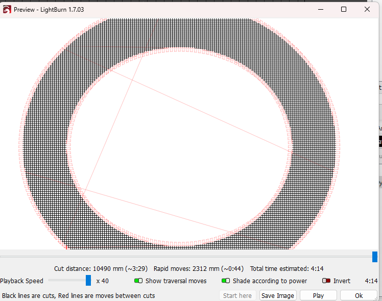
And thanks for testing it! You actually do have the same issue where it’s not cutting the edges between scan lines (they’re red not black) but it does indeed flood fill so you got me thinking that perhaps the small size of my part is a problem and indeed that seems to be the case, it was only 2mm OD. If I just scale it up by ~5x it transitions to doing what you show, this image below shows it in the middle between both modes though. It seems to enter a mode where it just connects lines instead of flood filling so it must be a tolerance setting I can’t seem to find that isn’t noticeable at larger scales. It should be noted though that this only happens with overscan off which is what I’ve been doing but I noticed you have overscan on and indeed that makes a difference, this small bridging goes away with overscan being on but I don’t want the overscan so I just set the % to 0 and that seems to finally flood fill my tiny shape properly so that’s progress! I didn’t expect turning it off vs setting to 0 to behave so different but that’s good to know.
That said, it still doesn’t cut the lines between the scan lines which is important and I also still haven’t figured out how to do the angle increment setting where it gradually rotates the scan angle which I’ve also found to be important. Any ideas on how to solve those two?
I still genuinely just don’t understand why the flood fill doesn’t work the same on BSL and GRBL machines, the GRBL flood fill seems simply broken to me which feels like the core issue.
I do not want to intrude into your proprietary project - just looking for some common ground.
Your scale issue is beyond my experience. The spot size and control resolution may be your Achilles heel in this exercise. I will continue to watch the thread, to see what the Borg mind collective comes up with for an answer.
They are different technologies. One thing you need to remember is that xTool has not been forthcoming in giving Lightburn all the info to operate their machines. Does it work as desired using XCS software?
While I’m looking to ultimately use this on an xTool I’m just using the default GRBL profile in lightburn to try and just get the preview correct with as few unchanged variables for now so that shouldn’t apply here.
XCS doesn’t seem to have a flood fill option and lacks a ton of basic things like arbitrary control of passes / line intervals and is super limiting unfortunately.
This new flood filling may work with the overscanning set to 0 instead of just off but I still need to figure out how to do the angle increment, is there no equivalent setting for GRBL machines? Any ideas on a workaround?
I thought to use sublayers for the angle increment and just have different scan angles but it seems to execute sublayers in sequence so it would just do all of them with the same scan angle back to back before switching to the other scan angle which isn’t super helpful. Is there a way to change the execution order or sublayers to be per pass instead of all passes?
While the machine does operate via GRBL, it is NOT standard GRBL like a gantry machine. I have no idea how xtool implements GRBL on a Galvo style machine. Way above my pay grade.
From the Google: While the F1 connects to LightBurn as a GRBL device, its galvo system and xTool’s software limitations mean that some features and functionalities are not fully supported or optimized, according to a post on the xTool Support Center. For example, features like embossing and certain advanced settings might not be fully available when using the F1 as a GRBL device.
The small size you’re working with makes it even more baffling for me. Sorry, I don’t think I can provide any more help here.
The only thing I can think of is using sub layers and changing the scan angle for each sublayer. I thought you said you tried that though and it didn’t work. Not sure why.