Hi everyone, I’ve been learning a lot from this forum, but this is my first post. Thanks to everyone for posting, this has become a very fun hobby.
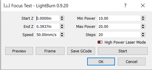
I recently upgraded to a machine with a Z Axis and have began playing with the focus test option. I’ve figured out most of the settings, but don’t understand what the Min Power/Max Power settings do. I’ve set them to various values but the output seems the same. When I examine the GCode directly, I only see the max power being set early on, I never see the min power being set.
I’ve tried enabling high power mode and the output seems the same.
Your min max comes into play with cutting and vector engraving. The laser automatically slows a bit as it comes to a corner or sharp bend. Many people will set a min a few percentage below their max for this kind of work. I know there is a built in table for circles and curves somewhere, but I’ve never taken the time to work with it.
On DSP controllers, Min Power is used as the power value for when the laser head is moving slowly. On GCode devices, that value is implied as zero, and the Min Power setting in that box doesn’t actually do anything at all. (It should actually be hidden if the device doesn’t support it, but apparently slipped through).
I will defer to Oz, I have a Ruida controller so I can’t translate beyond power percentages.
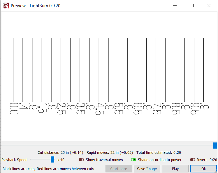
From that screen your unit is set to move the Z axis between lines to test proper focus. I have an electric Z, not a stepper Z. Even those of us that do use what’s called a ramp test. I cut Russ’ Focal Length ramp jig from his files, but you can manually do the same with some scrap. Get a scrap of something and put a rough 3/8" spacer under one end and set what you think your focus length should be at a marked center line. The run a low power line up the ramp from one edge to the other. The finest point is you best focus point. Measure that distance, I use a stepped focus gauge, and you’re all set.
Why do you like the ramp test better than the built in test? For the electric Z, is that simply something you jog up and down with no distance control? If so, I understand why the ramp test.
I’ve liked the focus test, I set it up for small .25 mm increments (or .5) and do the test. Use a magnifying lens to inspect the result and then jog the Z to the best distance. I start closer to the material than ideal so the test works from bad, to good, to bad again (like the ramp test). Had good luck the couple of times I’ve done it, but if the ramp test is better I can start doing that. I know it is ‘infinite’ or ‘analog’ in design, so that it a good advantage.
Never assume somebody has a stepper controlled Z or auto focus.
If you don’t have stepper controlled Z AND auto focus, then the ramp test is the only way. If you have stepper controlled Z, and have calibrated it, then by all means, use the built in. Many don’t have it, or have not bothered with or know how to calibrate it. My machine currently has a line voltage Z motor. Looking at converting it to stepper, but until then, I and anybody like me does it the old fashioned way.
You use a calibrated ramp and set what you think is your proper focal length at the 0 point. Run a line and verify. It can vary depending on if you set your lens curve up or curve down. Not a lot, but if you are going to be doing photo engraving, it can make a huge difference.
Once you know your focal length, use your stepped focus gauge to set it off your material and you are good to go. I have two sets of gauges with 1mm steps. One cut on the 1mm, the other cut on the .5mm.
What do you do when you try and engrave on a rotary? How do you set your focal point?
My machine is a Sienci Longmill CNC machine that I added a Diode laser head to (Sainsmart laser head). So the Z is calibrated (at least it will mill accurately so I have to assume it is).
I’ve not invested in a rotary yet, that is next on the list (or maybe as part of a CO2 laser). I don’t know if the diode will manage to engrave anything I would put on the rotary. I just got into this hobby in the summer with the Sainsmart 20x15 inch unit and then upgraded to the Longmill probably two months later.
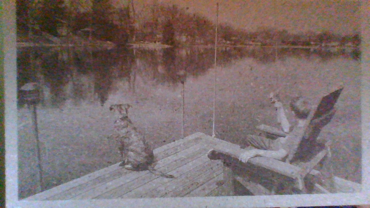
I’ve played with some photoengraving using the “Russ Formula” pages/documents. Once I got the Z motion, I was able to fine tune the dot size, but I have not tried flipping the lens around. Here is a test on MDF that I did after playing with the settings for a bit
You probably have one of the most accurate Z calibrations around of you are using a CNC base.
I can’t say on dot size for the lens flip, I do know Russ did some tests and showed it made a focal point distance change when flipped though. You’d have to scan through his videos on lens orientation, or drop him a question in one of his latest videos and he’ll tell you which one to watch.
95% of my engraving is vector, with almost all of the rest being raster lettering, I can probably count on one hand the number of photo engravings I have done.