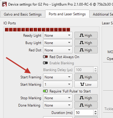
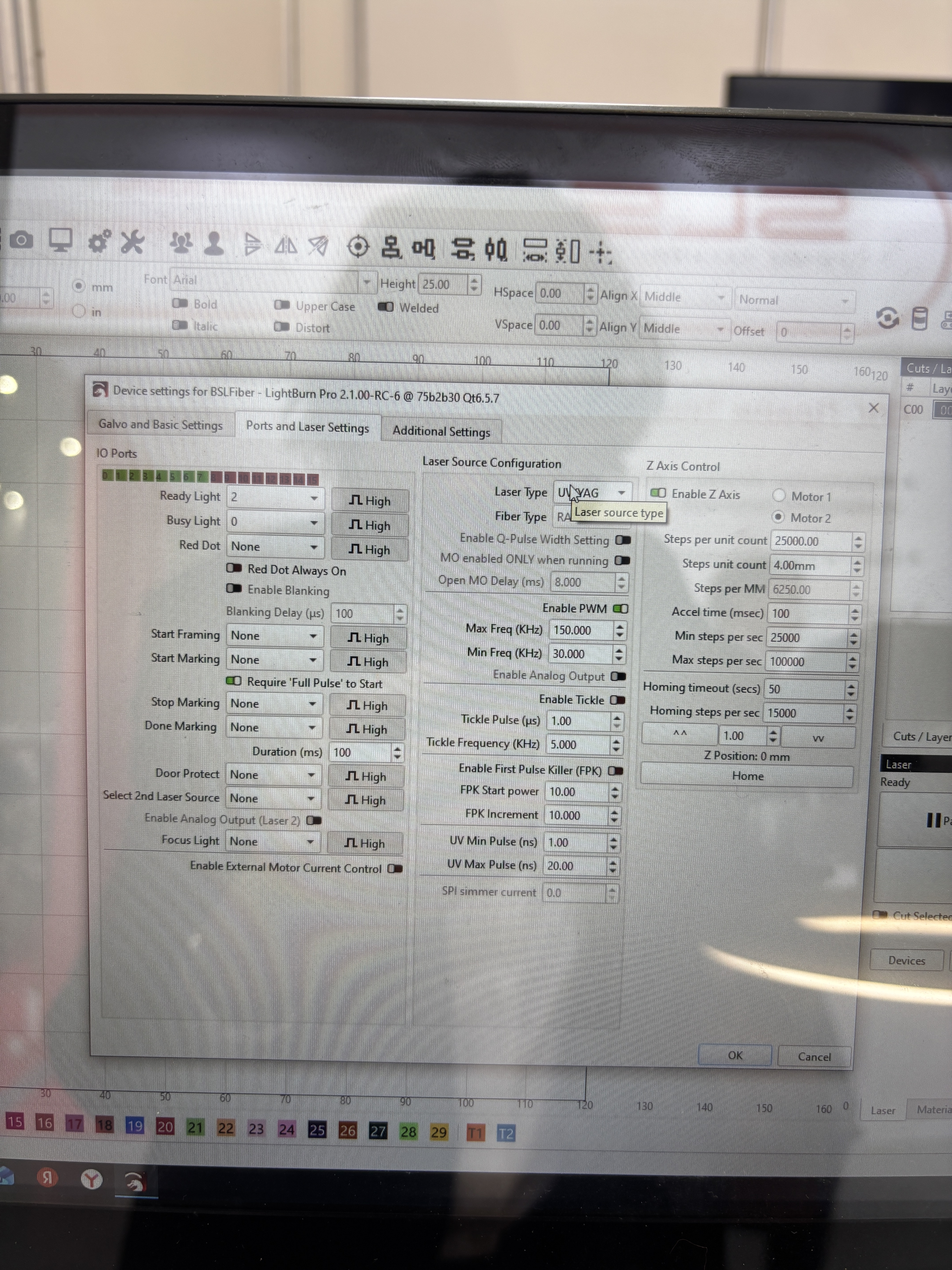
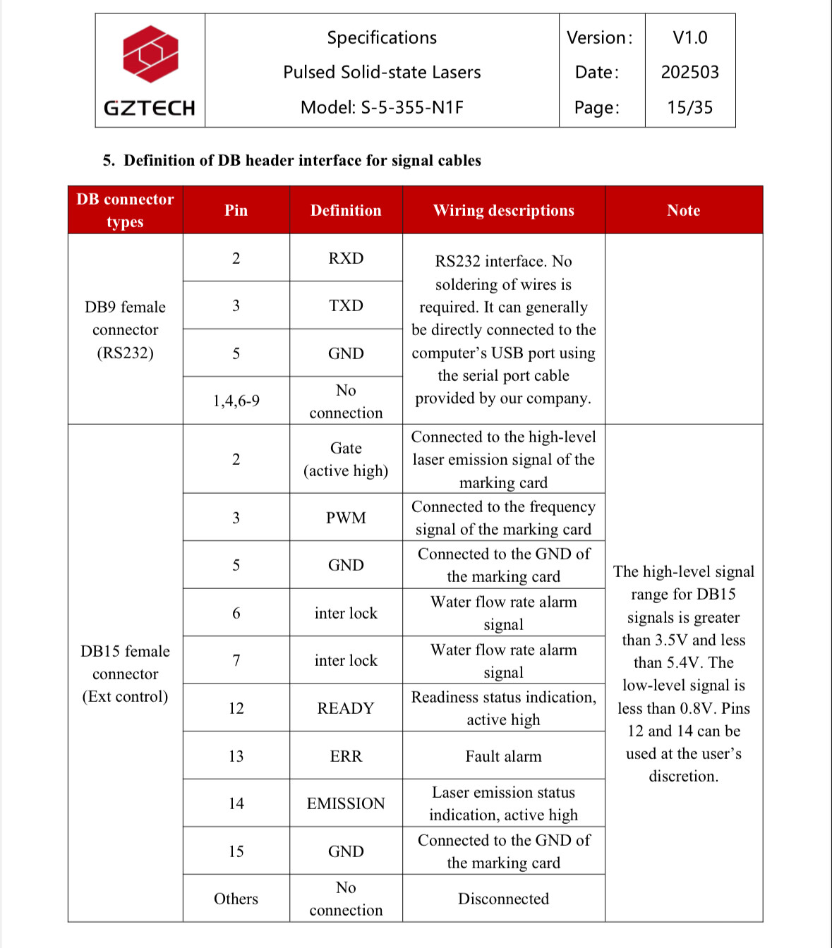
Framing dosnt work on bsl dbk22b(control board is new 2026), working fine with dbk21b(for fiber laser). Update: i use gzt laser, they use inverse gate, but in seacad 5.2.7 working fine
Update again. For gzt laser gate in framing must be 0, but in lifhtburn gate in framing 1 in marking 1 to. Near pin is redpt 1 in framing to
These pins are only used to start the framing with the pedal input of your controller. Framing should still work when you click the “Frame” button in the Laser window. Can you confirm this?
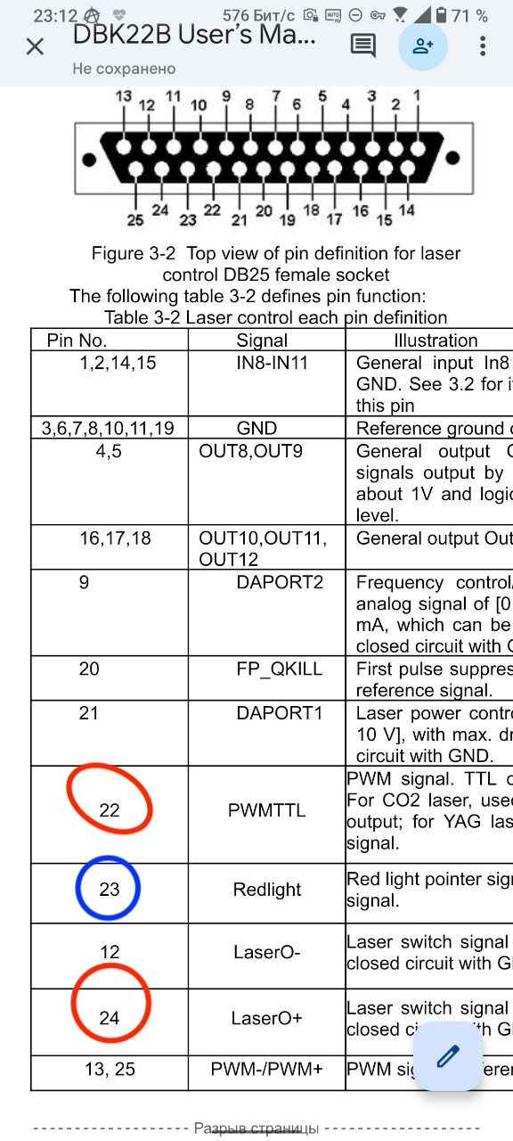
Yes, all ports disactivated. Problem only in dbk22b with Uv laser from GZTech. I asked BSL last night. They said the problem on lightburn side(maybe). When i click Frame, gate state is 1, but for GZT gate must be 0, set 1 only for marking. For example dbk22b have 2 pins for framing. Gate pin(must be 0) and Redpt pin(must be 1). Please check this information. I know that JPT has inversive gate. Now i only can use hardware for set in a frame gate is 0, for the difference use 1 in a Redpt. Thank you!
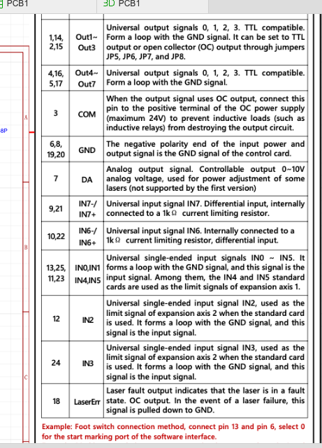
We use the following pins on the controller: pin 22 for PWM, pin 24 for laser activation (should be 0 when the frame is displayed), and pin 23, which is used in the controller as an alternative pin for the red pointer (we don’t have one). In Lightburn, when the frame is displayed, pin 24 is active (1) and pin 23 is also active (1), so the frame is not displayed. In BSL Seacad, pin 24 on the frame is inactive (0) and pin 23 is also active (0), but pin 23 can be set to (1) in the BSL settings. I can send video to you.
I think some trouble in SDK
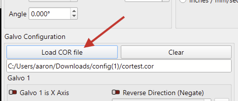
P.S. Cor files dosnt work too!
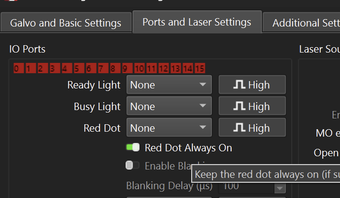
Hello! Yes galvo moving correctly. Problem only with LaserOn pin(high level when framing) I tried to check “red dot always on” and still nothing happened. About corfiles. Yes, cor work only in BSLcad. In lightburn cor files correctly work only with jcz board and ofcource jcz cor files. Thank you
I’m still not sure what the actual problem is.
Can you confirm that framing correctly works in BSLcad? Does it frame with the UV laser, or do you have a dedicated Red Dot laser on your galvo head?
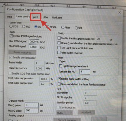
Please show us a screenshot of the “Port” tab in the SeaCad settings as requested.
Some of the settings don’t seem to be transferred to LightBurn correctly.
If I’m not mistaken, the “cortest.cor” file in the config.zip you uploaded contains the “raw measurements” rather than the hardware lookup table that’s being used by the machine. LightBurn would need to convert these measurements first, which it can’t presently do.
The file can be loaded in the Device Settings, but a warning should probably be displayed if an incompatible .COR file is loaded!
I’ll look into this and get back to you.
BSL decided to make their tool use the .COR extension as well, which makes things much more confusing (and it’s not something we control).
BSL’s COR files should work no matter what, because they produce the files, and we simply pass the files to their SDK for use. If the COR files you produced with SeaCAD or their tools don’t work in LightBurn, I can double check to make sure we’re passing the filename along correctly, but beyond that we don’t do anything with those files.
Also, worth asking - Have you run a job with the COR file set, or are you only looking at the red-light when framing? We had an issue in the past where BSL framing moves weren’t being corrected, but the running job was corrected.
For the red-light pointer issue, BSL has a function that we call to set the laser type, and when calling that function we also tell it if we want it to enable the red light. They have a separate function to “enable laser control” which to me sounds like “should the laser be controllable” not “should the laser be on”. Their docs and samples aren’t always clear - I’ll make a change and get you something to try.
As a test, I take one of the corners and shift it significantly to understand its performance. For example, I take point 1 with a coordinate of -50 50 and set it to -25 25, so I can see the distortion of the first point.
I also noticed some pin inoperability and signal inversions. For example pin 18 in lightburn pulled down to gnd in alltime. This pin needed only for engineers who produce marking machine, but i just report to you about this.