Hi - I have a Sculpfun S9 Laser which has been upgraded with limit switches, Sculpfun s500 Camera and 10w Laser cutter, I am using Lightburn (firmware for the machine is GBRL) and I am having the following issues: The camera image is off centre to the bed when I have calibrated and aligned the camera to the centre of the print bed and when I try framing a cut that is utilising 90% of the print bed the laser head tries to go beyond the printers frame - hope that makes sense. Any advice would be appreciated
I don’t fully understand. Can you show a picture and provide your settings? If the overlay does not fit to reality, you need to do the calibration again.
Some background information:
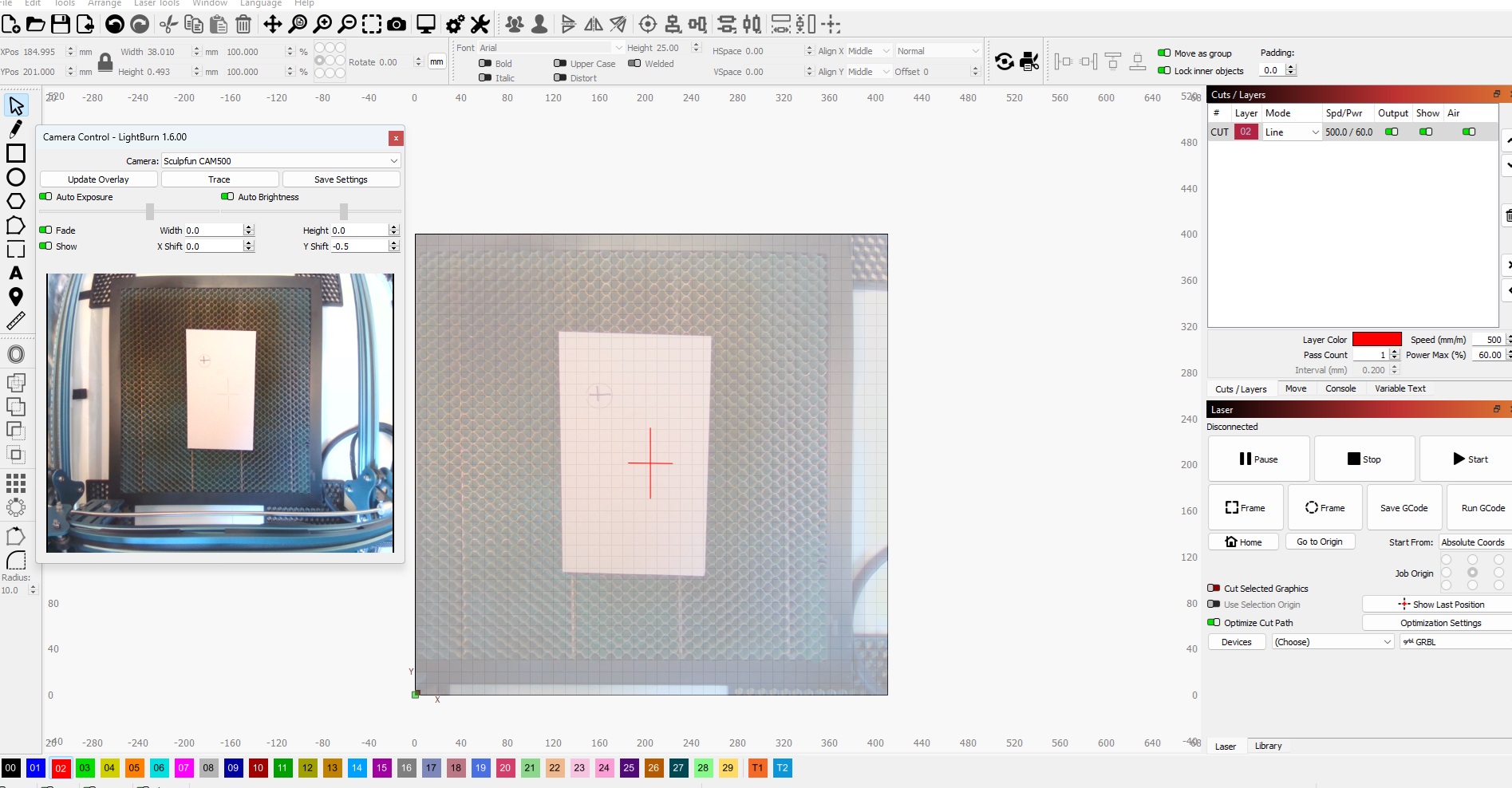
Here is the image of lightburn the image shows the camera centred on the cross which is in the centre of the print bed. As you can see the print bed is off centre and if I tried to print on the x axis at around the 400mm point the laser head would hit the right hand frame of the printer. The printer size is set to 410 wide and 400 height. So not sure its a camera issue but a calibration issue with Lightburn and the Laser printer
Which one? Both are not centered on the honeycomb, the small one is shifted to the top-left, the red one is shifted to the right.
Do not rely too much on the centering. It doesn’t matter where the camera is placed exactly. The alignment step will care about the position. Place the camera where you want it to be, do the alignment, and then you have a clear relation between camera and workspace. Of course, only at the specific height you did the alignment on.
It is the red cross that I am referring to, please ignore the smaller to the left, this was a test to see if I had aligned the camera correctly which I have. If I align to the centre of the print bed then tracing the image in Lightburn is way off.
I should also add that the red cross is centred to the middle of the Lightburn workspace, but it is way off when you look at the printer mesh (which is centred to the Laser)
As I said, do not pay too much attention at physical centers. First, the laser workspace is not centered in the frame of the mechanics. Due to the laser head size and the limit switches, the actual workspace of the laser is shifted to the rear right, compared to the aluminum bars of the laser frame. So don’t care about this.
After camera alignment, do an update of the overlay image. Then move the laser to the corner of the object you have in. Does it meet the corner? It doesn’t matter where it is displayed in the LB workspace, only the positioning between the image and the laser head is interesting. So if you for example, take the move laser function and move it to the small cross, does the laser head move there?
1 Like
Hi Melvin,
When I have centred the camera on the workspace, eg: the centre of the mesh when I do a test print to check for positioning I took the following steps. Placed a piece of wood on the workspace with a manual cross drawn on the sample, I then updated the image overlay and drew a circle around the image then printed. The result was a printed circle way off compared to the image I had drawn. The only way I can get this to work is to align the camera to the Lightburn workspace and therefore I end up with the lightburn workspace and camera image as the attached image in the earlier reply. So my question is there an issue with the calibration between Lightburn and my Laser printer, and how can I resolve this. Thanks
Try this!
Use a piece of scrap cardboard about 300mm square. Place it roughly in the centre of the engraving area. Secure it with tape or clamps. Cut out a square from the middle of the cardboard 200mm X 200mm centred in exact centre of your work area. Remove the centre bit, leave the “frame”.
Open the Camera Control and Update Overlay. Now draw another square that aligns with the cut edges of the “frame” image on screen.
Find the four numerical input boxes in the Camera Control window, called Width, Height, X Shift and Y Shift. Use the “View Shape Measurements” tool (Ruler) to determine the values needed for the X and Y Shift values to align the camera image position with the cut line. The size may need to be tweaked in a similar way.
I still don’t get it. You need to do the alignment. And that means, you need to align the camera with the LightBurn workspace. That’s what the LB wizard does. So that’s how things work…
This topic was automatically closed 30 days after the last reply. New replies are no longer allowed.