Hi all, new user of LB running demo here. I have given my troubleshooting the college try by myself, but am needing guidance at this point. My machine is an 2x2 MPCNC controlled by Raspberry Pi + Protoneer RPi CNC board. I am aware that Lightburn can’t be run on Pi, but that I can use a sender on the pi to execute the code instead of direct control through LB. My current testing is just to demonstrate that I get accurate XY motion control from the code generated by LB, I am just testing movement and am not actually using the laser in any of my tests yet. I have been trying to achieve this, but when I open my saved gcode in the sender (bCNC) I encounter these behaviors:
File takes extremely long to open (5+ minutes). For reference, my test image is a 3.5 MB greyscale bitmap, and the produced gcode is ~ 25 MB. I am unsure if this is normal or not–seems suspiciously large to me–but including for thoroughness.
bCNC fails to interpret the file correctly; instead of seeing the correct toolpath, I get weird skinny rectangles
stalling or knocking stepper motors at regular interval (every 15 sec or so)
Below are the 1st 60 or so lines of gcode. Note, the 500 mm/sec is in error; in GRBL I am set to 500 mm/min (so ~ 8 mm/sec)… but I don’t imagine that would cause the strange preview I am seeing in the image above?
I appreciate any and all advice…my brain is fried at the moment from testing and troubleshooting. I am tempted to purchase an Arduino Mega + Ramps 1.4 kit for like $40 to be able to run LB on the Arduino instead of using the sender, but I want to make sure I am not overlooking some simple novice mistake here in the software. Thanks
You can’t use LB on an Arduino. It’s a PC/Mac/Unix app.
Although, saying that, I bet my new Pi4s can, with suitable linux tweaks.
You should just set up a network drop box to be monitored by the Pi for a gcode file. Create job on LB, save GC to dropbox.
Start with something less strenuous than a 25MB file. How long is your job? I suspect a couple of hours - think of how many back and forth lines need to be described: a solid 0.1mm beam scanning over 10cm equals 1000 instructions. Add in a greyscale image where the instruction may only cover .3mm before changing power or direction and 25MB isn’t crazy big.
This is a series of 3 boxes on a 300x200mm bed. See what that does.
Thanks for the response! Yeah forget what I was saying about Arduino, I mis-represented…it seems like most people with MPCNC use Arduino Mega + RAMPS 1.4 so I was musing the possibility of all my problems being solved by switching to another board . Unsure if its the same situation as the Pi where gcode needs to be send to the Arduino over a thumb drive (or shared folder like you suggested), or if the Arduino can be connected to a PC. Obviously I’ve never used Arduino before.
In any case…
Your point re: starting simple was well taken. My end goal here is to engrave photos, so I jumped the gun. Tonight I drew some simple hexagons in LB, and lo and behold they executed perfectly. So I’ve demonstrated in principle that I can produce usable gcode in LB, carry it to the Pi, and have my machine execute it.
After that, I reattempted to my photo test, but with the image shrunken down for speed this time. Filesize of the gcode was only 3.5 MB this time. Issue still persists… the sender (bCNC) interprets the file as a solid black rectangle. I decided to run anyways just for kicks, and yes it began to burn a solid black rectangle. What’s more, it estimated 22 hours (!) to complete, which considering the original file is 90mm X 100mm seems unlikely to me.
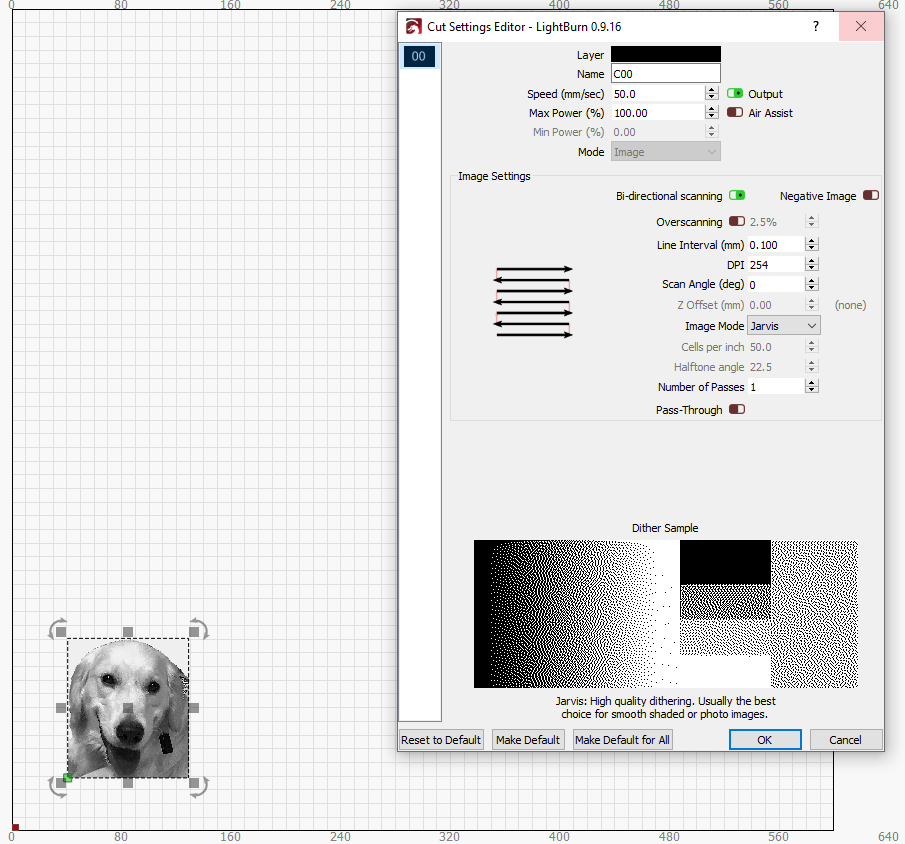
So, this all tells me there’s something I’m screwing up or otherwise going awry in my setting of image engraving settings vs. simple shapes. I’ve attached a screenshot of my cuts setting and the design.
Start from the beginning: what controller do you have, what version of firmware is it running, what laser do you have, what are your machine dimensions?
Edit: ok, I’ve looked up the protoneer CNC Hat.
I’m not sure how much I can stress: 8-bit arduino CNC controllers aren’t up to the task of laser engraving. They don’t have the speed or memory enough to deal with a GCode stream that might have 1k of commands in a few milliseconds.
Perfectly adequate for cutting wood, can’t keep up with engraving photos
You can also take your saved GCode file and run it in an online simulator, which will prove that the gcode itself is correct. LightBurn uses all relative moves for fills and images - is it possible that bCNC doesn’t like those? If you draw your hexagon again but set it to fill, does that work? The gcode used for images is nearly identical to simple filled shapes.
Raspberry Pi 4, Protoneer RPi CNC hat v2.6 (current), GRBL 1.1. Machine is 600mm X 600mm, though my test engraves are well below max dimensions. JTech Photonics 2.8w laser: https://jtechphotonics.com/?page_id=3819
I’m not sure I understand your comment about Arduino controllers correctly. I understand that they are lightweight, but there’s a number of people successfully using Arduino Mega + RAMPS (not my board, of course). See: https://www.youtube.com/watch?v=gfq60hYdKHM
Thanks Oz, I’ll give the filled-hexagon test a go here shortly. What’s odd here, is that I created gcode for the same exact image using Image2Gcode, and the same thing happens: the file is interpreted by the sender as a solid black rectangle. Even more odd, I have used 2 different senders (bCNC and Universal Gcode Sender), with exactly the same results… this makes it harder for me to “blame” either the code generation software, or the sender… I fear there is some glaringly obvious process step I’m missing
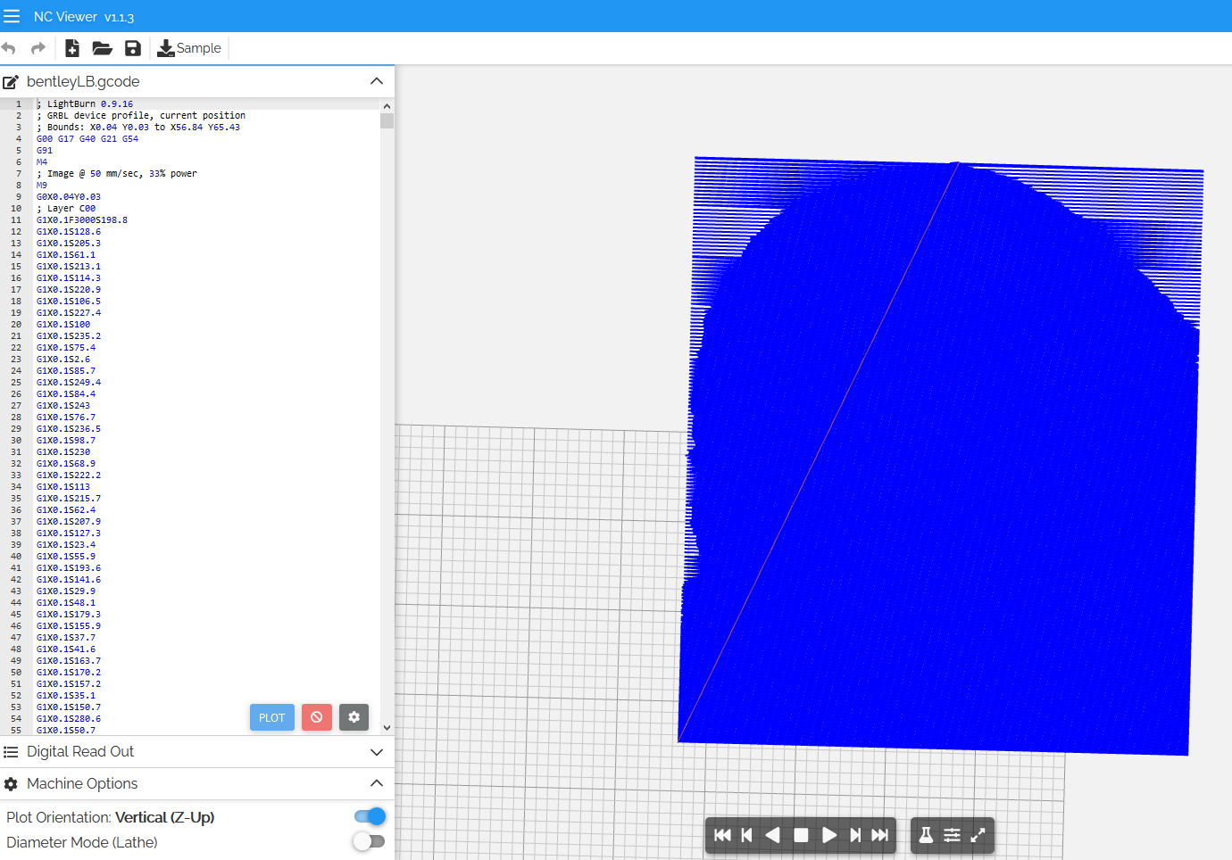
I’ve run the code through NCViewer, and while I cant make out all the details, it does render a square roughly same proportion as my input picture, and I see some curves along a voided space where there is a large white area in the my file… in other words, the code seems to be intact or at least the basic outlines… See below, not sure to what degree of resolution I should expect from an online code viewer such as this, but you can see the curve at the top of the plot corresponding with the dog’s head
Ok Oz, I have the ‘filled hexagon’ test underway. bCNC recognized the file dimensions just fine, and is filling in the hex line by line. Looks like it’s working perfectly.
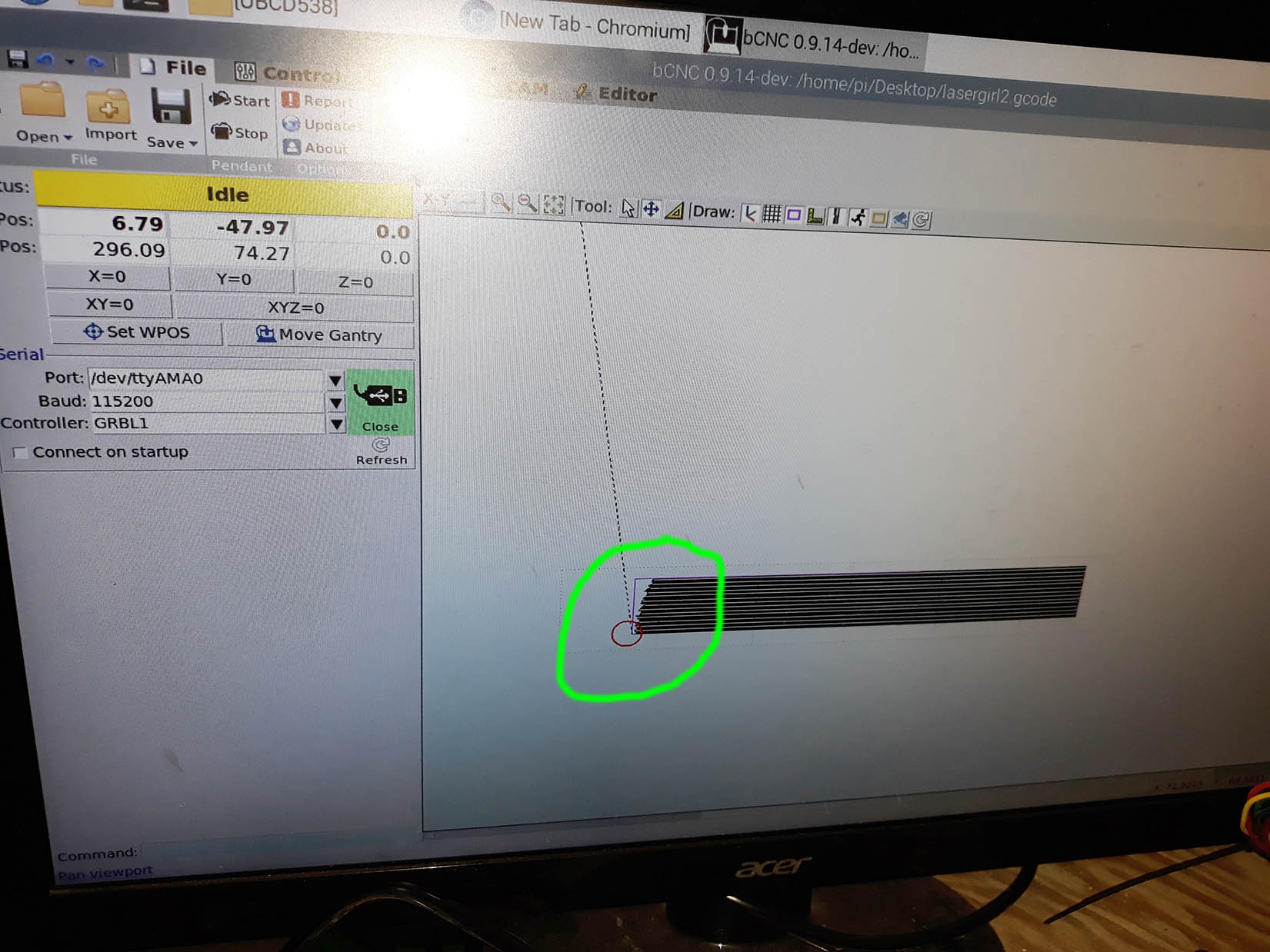
A big clue with the image engraving tests is that I noticed that bCNC does not preview the images as true rectangles, rather it looks like it recognizes the gcode file, but compresses the y-axis such that the whole image has been shrunken down vertically. See attached photo, with area encircled in green.
Success at last, I now have the engraver laser functioning properly. In the words of Blind Willie Johnson, “aint nobody’s fault but mine”.
The board is fine. The software is fine.
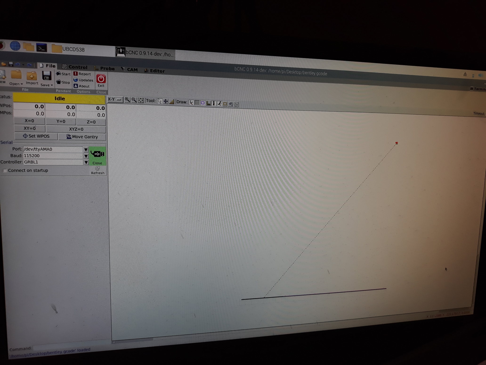
The silly rectangle business was a result of bCNC’s interface. There is a ‘timeout’ dropdown in the top righthand corner. It stops rendering the preview after n seconds, so changed it to infinite, and it displayed the toolpath correctly.
I neglected to set $32=1 in GRBL at the beginning, was left at =0
bCNC has an adaptive laser mode, which I checked.
I think I had laser cutter selected, which I’m guessing didnt allow variable power to create shading, thus just doing solid burns everywhere.
I ran a 50mm x 70mm test image just now, and while the quality isn’t perfect it demonstrates excellently that I’ve got the engraver functioning properly. Thank you both for your help in troubleshooting, I am ecstatic to be on the right track!
 . Unsure if its the same situation as the Pi where gcode needs to be send to the Arduino over a thumb drive (or shared folder like you suggested), or if the Arduino can be connected to a PC. Obviously I’ve never used Arduino before.