Getting a smooth fill with Omtech Polar 350

I am still in the learning phase for the CO2 world. I am attempting to do a fill on some text on some 3mm baltic birch plywood for a set of earrings. I have finally matched the shade/color I had on my diode. The issue I am having is I can see what looks like lines instead of smooth color shades. Is this a case of the speed being a bit fast or should I look at tweaking the power?

An example would be
400 mm/sec
45% power

It leaves visible lines on the shading if I look closely whereas on my diode it was a smooth color/shade with no visible lines.

Thanks,

Henry

What line spacing have you chosen?
If it is at approx. 0.075 mm, I can no longer keep the lines apart optically.
400mm/s for smaller items is too much in my opinion, but I don’t know your machine…
In general, I could not use some of the setting experiences from my diode machines on my CO2 machines, everything had to be rebuilt from scratch. I did a lot of testing and tweaking until it worked for me, but it was interesting and fun.

Remember to update your avatar information :wink:

I will check the spacing and report back. I have the Omtech Polar 350 that I am trying to recreate the look and feel from my Longer B1-40. I am having the same issue with not being able to use any of the settings and like you say a lot of testing and tweaking. I see there is no shortcut on the learning curve and with my old diode, I had over 2 years of experience spanning over two machines.

Good catch on the avatar info…

Henry

Although the image quality of my old 5.5W diode was quite neat, I can produce fine quality with my 60W CO2, the biggest difference is that the focal point is round and the spot itself is smaller on my CO2 laser.
NB. Congratulations on your new machine

I will have to check the size of my Polar’s laser compared to my Longer. It’s so weird upgrading I now have a Lamborghini (Polar), but I still want to drive my Lincon Continental ( Longer)…LOL.

Is this what you meant about line spacing? Should I bring down the line interval and bump the lines per inch up?

Henry

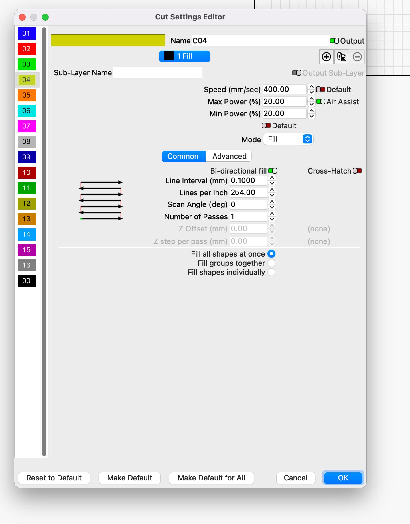
What interval are you using?

Most co2, with stock lenses, struggle to get a 0.20mm spot, limiting resolution to about 128 dpi.

Machining is machining, cnc just adds a computer to the mix … the actual tool operation may vary but the rest of this is the same. The led and the co2 effect are very similar as far as power and damage to similarly absorbed material, such as basswood.

Figure out what’s going on at the beam → material point. What exactly is the beam doing to the material…

An led is on or off. When you send it a 50% pwm signal, it is on 100% for half the time and off the other half. It’s a digital device… This would relate to 50% power, although it’s really power/time.

A co2 can operate at 50% power continuously… if you set it for 50% power, the lps limits the current hence the output power. A glass tube co2 is an analog device.

You might want to limit your speed, for more than @ednisley mentioned and ensure you’re using a reasonable interval for the response time of your lps…


The minimum response is usually placarded on the lps and is usually 90% output voltage <= 1mS (1/1000 of a second).

If this is the case and we use the worst case 1mS value…

Running at 1000mm/s will allow you to toggle the tube every mm, the best resolution would be 25.4dpi…

If you slow down the 500mm/s, it can react twice every mm and the best resolution would be 50.8 dpi…

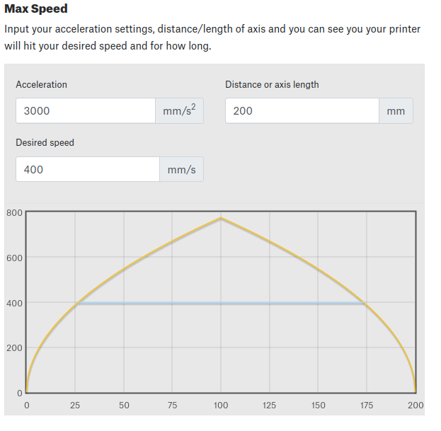
Just keep these in mind… hang in there, I’m sure you’ll get a handle on it. I’m with Ed, I think you need to slow down a bunch. You can figure out how much room it takes to accelerate to maximum speed using the calculator.

Good luck

:smile_cat: