It comes with the SoftAP( AccessPoint ) version of the firmware installed so installed the Station version which connects to my existing network WiFi router. So now it can be accessed from a known IP address on the network.
Then I used Gstreamer to create a dummy video device( /dev/video1 ) based on the IP cam address:
gst-launch-1.0 souphttpsrc location=http://192.168.1.222:8080/ ! jpegdec ! videoconvert ! v4l2sink device=/dev/video1 sync=false
And now, LightBurn for Linux attaches to the camera like it was connected locally.
I don’t have the camera permanently mounted yet but in the picture it is just sitting on top of the K40 looking through the window. It looks like it can stand to be a little closer so I might make a protective holder and mount it inside the lid powering it by the same 5V converter I used to power my red dot laser.
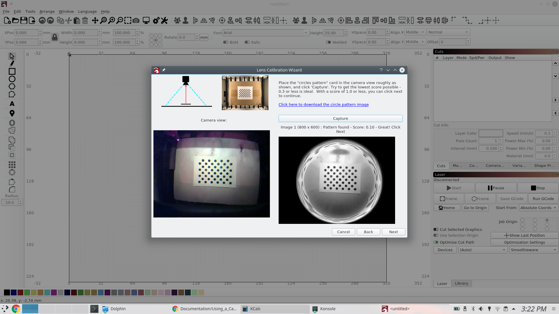
But I seem to be running into an issue. It sometimes acts like it’s got a fisheye lens on it no matter if Standard or Fisheye is selected. Get different results after stoping LightBurn and restarting.
This means you’re probably basing your observation on a noisy data set with a sample size of one, instead of going through the rest of the calibration process and letting it fit the calibration to the entire set.
I also notice your card isn’t mounted to anything and the paper is possibly curled a little. If that’s true, it’s going to confuse the hell out of the code trying to model the distortion of the lens, as it’s expecting that pattern to be absolutely flat.
My first posted image was originally just to show I have the IP camera recognized by LightBurn. I had quickly clicked the link for the calibration circles file and printed it from the browser and that resulted in a full page of dots. I just put it on the bed of nails and took a screen shot.
Then I read the description of what the image size should be so I brought it into Inkscape, made a box the proper size and made sure the dots fit into it and then printed that. At this point I put down a piece of plywood on my bed of nails and placed the calibration card in the center. I took lots of tests as I adjusted the camera location and angle and initially the Image 1 process worked well. It was when I tried to do the 2nd shot where things went haywire. I moved the calibration card to the edge of my working area and got no image on Capture button press. A number of retries then started showing the Image 1 step looking like a fisheye when it wasn’t selected.
I’m wondering if the calibration card has to be at the edge of the image area instead of the edge of the work area… But either way, I don’t now why the first step, Image 1, would start showing the fisheye results.
I also notice that when I try to Capture, the live Camera View will freeze and I see an error on the console:
reqID 1
“Image 0 (800 x 600) : Pattern NOT found - try again”
CameraBin error: “Failed to allocate a buffer”
CameraBin error: “Internal data stream error.”
I was hoping to test this on a ubuntu 16.04 bootable iso but I can’t get a trial license any more as it complains about tainted system clock/time even though it is showing correctly.
I started this effort when I saw your post about how to align a project for working on the reverse side.
That looked really cool and quite handy so I figured I’d see about getting a camera working. That’s when I remembered my MacBook Air only has 2 USB ports and I use one for the laser cutter and the other for xfering files over USB thumb drives. Then I remembered about the esp32 cameras I had. I got all the way to uploading firmware and figuring out how to create a virtual device from the IP camera address.
If it can be made to work it’s a nice solution since it’s cheap, requires no data cables and only needs 5V to power it.
Putting a cheap USB hub on the Mac would let you connect the camera and controller through a single cable, rather than jumping through a lot of extra hoops. You also only have 800 x 600 res, though for a K40 that should be enough for 0.5mm accuracy.
You still haven’t said what you did with the card, aside from “put it in the center” - It’s recommended to glue it to foam board, MDF, plywood, etc, so it’s really flat. Any curvature in the physical card will be interpreted as lens distortion to be corrected.
I have a wide angle USB cam I was going to use on an autonomous RC car but will use to see if things work any better off USB. I know I have a USB2 unpowered hub around somewhere and will try that.
I didn’t attach the calibration circles printout to anything because I put down a flat piece of plywood on the bed so it lays flat. Disregard the first picture as that was just a quick print, capture and post and not even used to try and calibrate. When I was ready to try to calibrate, I read the instructions and noticed the size was completely wrong.
So the “white” box( the card ) size is what’s important and needs to be how close to the specified 148mm x 105mm?
The circles image will be approximately 148mm x 105mm (5.8" x 4.1"), and should have at least 6mm (1/4") of white space around the pattern.
The other thing I was confused about what if the movement of the card was within the camera view( ie center, edge to edge ) or within the laser cutting area( the bed )?
Note: This process is dependent only on the camera and lens, not on its placement in your machine - as long as the camera and calibration pattern are perfectly still, you do not need to mount the camera in the machine to perform the lens calibration. If the calibration image cannot be held at the appropriate distance to match the shown image in the display, you may shrink or enlarge the printed pattern.
The images/instructions in the application are different and those are what I figured was current.
See the dialog boxes open in the 2 images I posted at the start of this thread.