80 watt Redsail RUIDA filled line art engraving. I developed settings using test grids. No matter what I do, the edges always have some random blowout (clear glass broken away from main structure). What can I adjust to mitigate this problem. These are glass panels for cabinet doors with large grapics.
Perhaps the glass sheet is cracking due to thermal stress.
The laser deposits (a tremendous amount of) energy into the engraved area, the temperature goes up, the middle of the sheet expands more than the perimeter, and it cracks.
@jkwilborn found that out the hard way while engraving a slate sheet:
If you can’t change to a stronger glass, then you must reduce the amount of energy dumped into the sheet. Dividing the overall pattern into smaller sections and allowing the sheet to cool between each section may reduce the stress enough to get through the job.
How large-area engraving will affect the glass sheet’s properties in use is a good question. If the engraving leaves residual stresses, the whole sheet may shatter when somebody slams the cabinet door.
Maybe this is a job better done with acrylic panels, rather than glass.
Do you mind posting the speed and power you’re using?
Any damage on glass is, in effect, shattering the material.
Since both the laser and the materials are variables, we’d have to know more about it.
![]()
I confirmed with the glass supplier that this is not leaded glass. I have used engraving processes with and without dish soap to reduce surface heating. I ran multiple scenarios with LB test grids and a microscope to determine the best settings for my 80-watt CO2 laser with RUIDA G6445 control. The grayscale/image file gave the best results overall. However, all tests showed the edge blowouts as seen in the photo attached. The photo shows just a sample edge. These clear sections are very visible and are sporadically place over the whole graphic. They do not show up on the interior of the filled lines. The client is an interior designer and will spot a flaw like this immediately.

I confirmed with the glass supplier that this is not leaded glass. I have used engraving processes with and without dish soap to reduce surface heating. I ran multiple scenarios with LB test grids and a microscope to determine the best settings for my 80-watt CO2 laser with RUIDA G6445 control. The grayscale/image file gave the best results overall. However, all tests showed the edge blowouts as seen in the photo attached. The photo shows just a sample edge. These clear sections are very visible and are sporadically place over the whole graphic. They do not show up on the interior of the filled lines. The client is an interior designer and will spot a flaw like this immediately.

I misunderstood “edge” as being along the edge of the glass sheet with larger fractures, not surface chips along the pattern borders, but the problem remains the same: too much energy deposited in too small a space.
The large clear area in the photo looks like it happened during three separate raster passes, as it consists of three separate fractures.
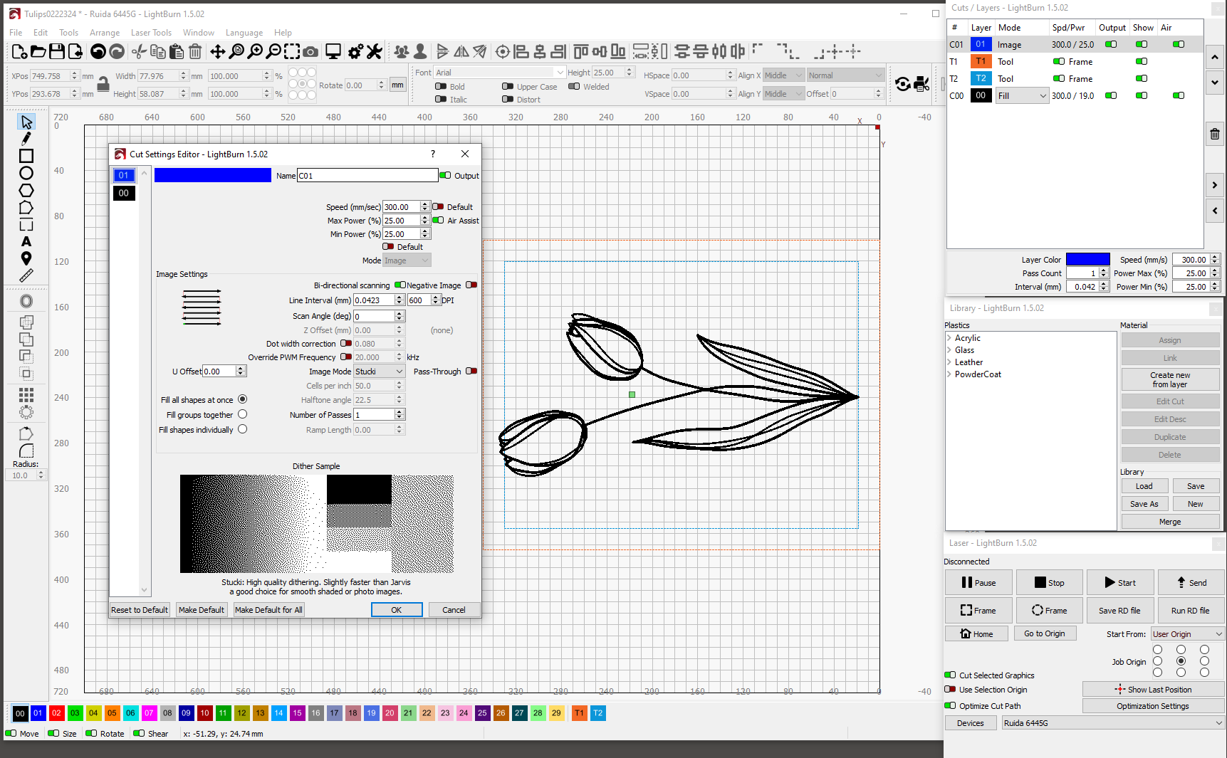
The cut settings indicate two active layers:
C00= filled vector @ 390 DPIC01= Stuki image @ 600 DPI
What benefit does hitting the glass with two different versions of the same pattern produce?
The line intervals seem too small, given that the typical CO₂ laser spot size will be on the order of 254 DPI = 0.1 mm. Smaller line intervals dump more energy into the glass under adjacent lines, which may contribute to the larger fractures due to localized heating next to adjacent cooler glass.
Perhaps a wider line spacing will reduce the chipping by depositing the energy along non-overlapping paths.
Leaded glass is different from tempered glass, which shatters differently. Although non-tempered glass (either ordinary or leaded) is annealed, it retains localized stresses that may be contributing to the small-scale shattering.
I experimented with engraving tempered glass a while ago and concluded I didn’t know enough to make it work, but the the results have tidy pits without the large-scale chipping of your results:

I think a dithered image (without the filled vector duplicate) at about 0.1 mm line spacing on tempered glass would work better, but there’s certainly room for considerable improvement in my results. ![]()
My apology for not being more clear about the history of this problem. I first started out with filled lines. When that did not work after many tests, I switched to an image file for testing. Dithering has helped to improve the quality of the process. I will repeat my testing with lower dpi. I see the results in your photo and that looks like it might be the solution. Have you experimented with defocusing for photo engraving on glass?
Not at all, as I was killing an old glass shelf that had the misfortune of emerging while I looked for something else.
I suspect a dithered image looks better than a simple fill because each dot produces a separate glittery pit, rather than a trench. If that’s the case, then Halftone or Newsprint dithers may look better on glass than on, say, wood, because they tend to break up solid color areas; Jarvis (and similar) allow solid areas that may be overheated and spit out large chips.
With that in mind, a defocused dot may either produce a bigger pit (thus overlapping with adjacent pixels) or reduce the energy below the level where it damages the glass (thus producing no image at all). It’s certainly worth investigating, but it will introduce Yet Another Variable along with speed / power / interval.
I think this is somewhat unavoidable when using heat to break glass. Glass engraves in a laser by blasting out little chips, in tiny explosions. The heat generated will exacerbate any stresses in the material (including those it introduced when operating nearby) and create these larger chips. This happens even when cutting glass by hand, sometimes glass just does what it wants to do.
I agree that dithering an image that is made of a grey that is 75% black may look better, you could also try a cross-hatch pattern by widening the DPI until large gaps appear between the scan lines, and running two passes, each with opposite scan angles (e.g. 45 and -45), you might also want to try backing off the power.
Been following this …
I’m not really sure what you’ve done … let me give you how I’d attempt to analyze this and you can do with it what you want.
Using glass you can’t get it hot enough to vaporize, it reaches it’s thermal structural limits and shatters. The initial break can cause other physical stresses that can then cause a failure (shatters) in other areas.
I’ve done this for a few years and found that a good view of what the machine is doing to the material is the best place to start. Good photo. It would be nice to know how much room you have or how large the image it… There is a difference if the machine going over a small area heating up or a much larger area where things have a bit of time to cool down.
You’re scanning, which way is it moving? Top to bottom or bottom to top?
First thing I noticed is a different looking texture from the center to the left of the good part. This can sometimes be caused by the magnification process. I’d expect it to be more consistent. You can advise.
The larger chip could be caused by the engraver moving from top to bottom and the area is ether pushed out because of stress or it has a flaw in the glass it self. You could also summarize that it’s heating that area and this flaw cause the whole area to chip out…
This questions the fact if it’s pushed out or thermally broken, why isn’t there engraving damage after it chipped out?
What you might not see is that there are other large pieces missing, but subsequent passes make them difficult to see.
I’d suggest
- make it one pass
- using a lower power or higher speed.
- work with the interval
Most of the people posted good suggestions.
If you use a scan angle of other than a 90 degree multiple, the hardware control is lost and Lightburn has to generate the moves… They don’t recommend it…
Some people claim rules are meant to be broken, in the end whatever works.
1 Like
First of all, thank all of you for responding with your suggestions. My image is a thick line drawing of tulips (about 2mm~3mm wide lines). It is about 12" x 18" and I am processing the image along the x-axis at 0-degrees with air assist. I am about 90% successful right not. I will employ your suggestions with both fill and image type files and report back. Thank you again.
1 Like
Newsprint setting did the trick. I will play with power/speed a bit more to see if I can get a deeper frost appearance. Thanks again for all your help.
2 Likes