Yes very undersized. Most of the first belt tensioners on had a 4-40 or metric equiv. screw going thru the bearing. the bearing itself was micro even the new one that i just bought for a 15mm belt is tiny. whoever is designing these thing are going as cheap as possible. luckily the GT3 belts i have been using are steel reinfoced or else i would be going through them too!
@jkwilborn any idea on how i can get rid of the scan lines on the left most and right most edges. Right most vertical lines shown.
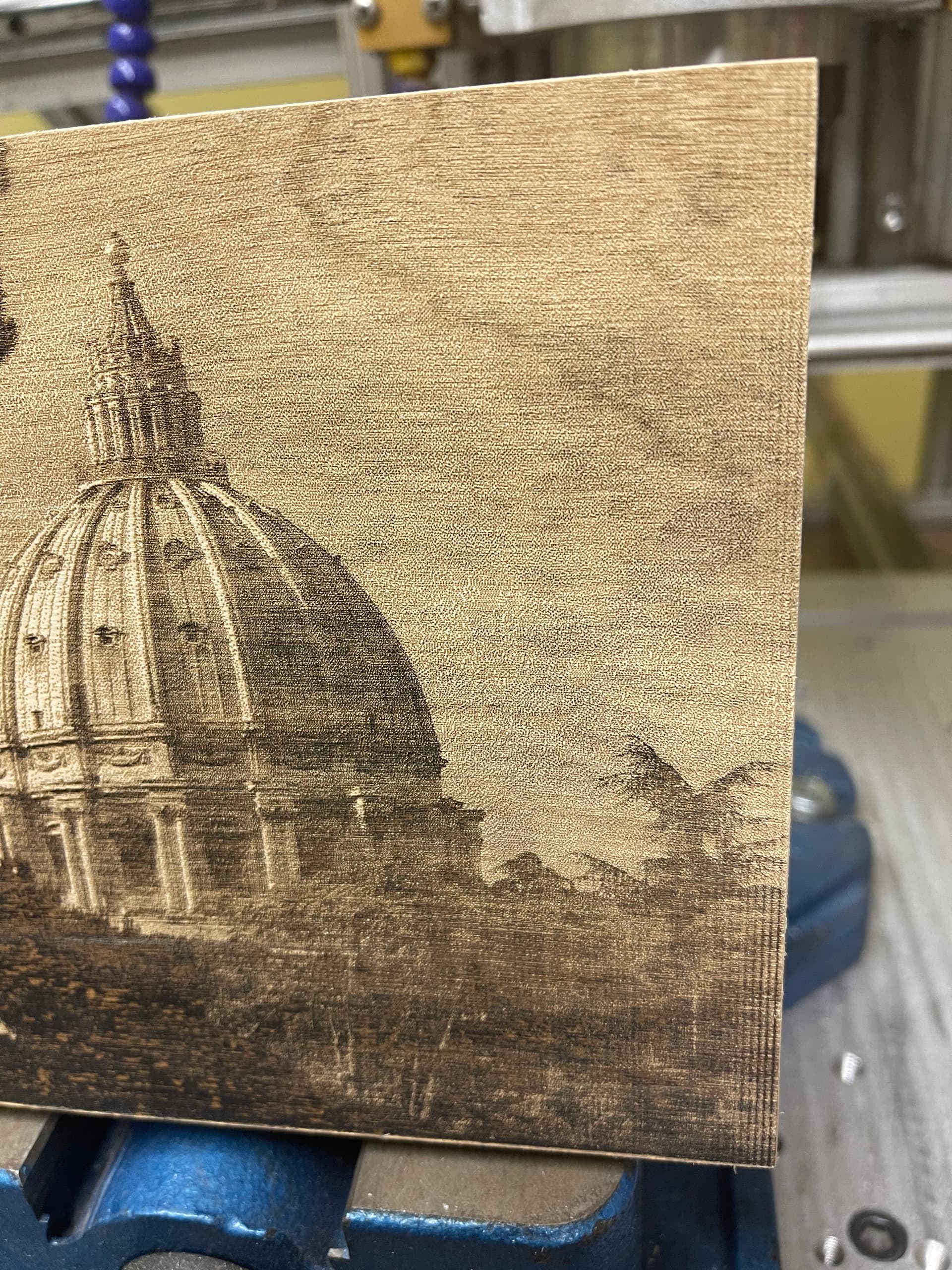
only see this on left and right not through the center. Not sure what setting might correct it? Any thoughts?
Looks like Moiré patterns. When you zoom in it looks rather normal as far as power/speed.
Maybe a combination of pattern and dpi/lpi.
![]()
this was done at 200 DPI. The original photo has no signs of any artifacts. Its seems more like the start and stop of the scan switching direction, just not sure what to change to correct it. Only running @35mm/sec.
May of actually just found the problem didnt notice it on earlier ones because i didnt have the diode laser mounted then. I think its slight vibrations from the diode laser as they are connected together. Will know in a few minutes.
With a moire’ pattern, it’s generally not related to the original. When you ‘dithered’ it or had it digitized with the effect of the moving ‘print’ head creates these patterns. I have changed dpi and corrected it, speed might also, but it looks pretty good at that speed/power.
It looks real good, is that the grayscale mode?
If so, what kind of material and speed/power… I’ve been really struggling with that on acrylic…
![]()
No this one was the jarvis! 35mm/sec 20% power Co2. im gonna run one of the Eiffel tower tonight. Picture my folks gave me of their trip. Going to try and make this one a 3D one. Been running alot of stuff on 3/4" cabinet grade maple plywood. Eiffel tower will be on solid hard maple!
I see what you mean now just went to look at the preview and when i zoom in i can see that pattern. I will trying changing DPI on the Eiffel tower.
You better post photos of them or we’ll send in the gremlins… ![]()
![]()
lol i will add them to the creations thread and flag ya down ![]() wait till ya see the 3D owls! They are what start this craziness!!
wait till ya see the 3D owls! They are what start this craziness!!
I use this belt when I replaced the belt drive on mine with Russ Sadler’s ‘rack & pinion’ system. This was his suggested belt.
1 x AT3 Standard Breco® Open Length Timing Belt (1742) = £28.48
Width in mm 15
Length in metres 1.500
Nylon covering Not Required
Tension Cords Steel
Material Standard 590 White PU
It was so expensive to ship it to the US that Russ purchased it for me (I paid for it) and packed in his kit when he shipped it. I can run 1650mm/s+ when I’m ‘fooling’ around.
These are what I’ve modified… so you can get an idea of how ‘loaded’ the belt could be.
The lightweight head modification also enlarged my ‘work area’
It could be larger, if the screws for the Z table were not in the way. Be nice to change that so they went out the bottom… give me more room.
![]()
what are you using for roller bearings and timing gears? have you upgraded them or were they original? i havent pushed speed too much yet as i need more cross braces on left and right side of the machine. im moving fast enough to pull a few G’s though.
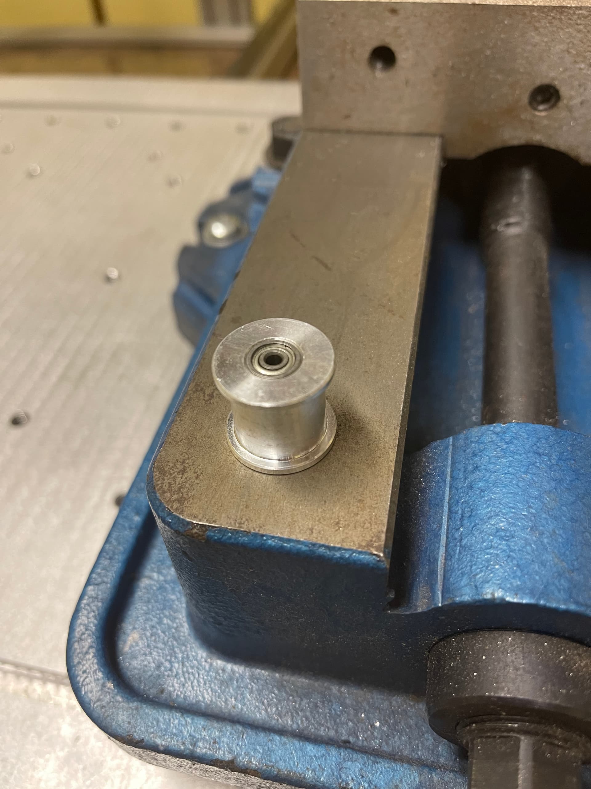
The bearings from Russ are good, the right hand tension roller is pretty sad.
Here was his price list a year or so ago… to give you some idea of the parts he makes.
The high speed is only good for experimentation, not much useful. You are running so fast I don’t think the lps can keep up with you trying to lay down dots.
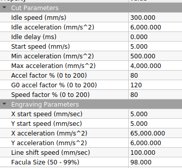
I have set my pwm frequency to 1kH and at 50% power, looks like a fine line at 500mm/s, but at 1000mm/s you can see the dash marks from the laser turning off/on.
Definitely learn something…
![]()
@jkwilborn Nice Thanks that info! I see what you mean about the speeds! I dropped my start speed this morning to see it that might be the cause to my vertical lines im getting on scans.
I doubt it will have much effect. When you scan, the machine ensures you are up to speed before the laser can fire. It may increase the overscan.
![]()
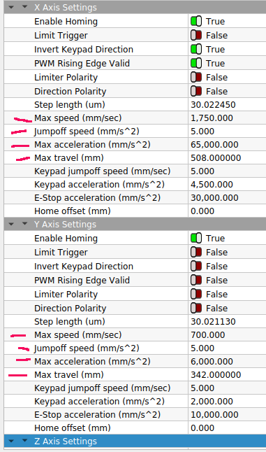
What are you running for start speeds for X and Y? I have been set at 25.4mm and was thinking of dropping it to 2.54 to see what it did. Took me a few weeks until i had some decent values. The values that were in the ruida when i got it were crazy.
![]()
Wow your accelerations are way up there compared to what i got. How big are your motors (Nema Size)
Nema 24
It’s less of the motors than it is there is little mass on that axes to speak of.
I have no drag chain or all it’s associated hardware/hoses/wiring. All that gets drug around is the air hose, virtually no mass.
The lightweight head removed over half the mass of just the head assembly… I think it was about 220 grams and now it’s about 100. That doesn’t include some of the brackets I had previously cut off.
This also lowers the mass on the Y axes. I put some of that back on with the ‘rack & pinion’ option from Russ. It’s still lighter and I have been running it’s acceleration at 6,000mm/s^2 up from 4,000. Fifty percent increase in acceleration.
I keep pushing the speed and acceleration values. They are in ‘balance’, you can go faster with less acceleration, but you pay for it with increased overscan. I prefer the higher acceleration values for vector engraving. More speed control in the small areas.
Here’s a video, you can see there is little to drag around.
It’s the back of a 12"x12" mirror tile. Here’s the finished product…
If you are trying to lay down ‘dots’, depending on the dpi, you can very easily ‘outrun’ the response time of your lps.
Take care
![]()
@jkwilborn does your roller bearing on the left of your X axis have teeth or smooth. I am making up a set of new bearings for my 15mm belt. I heard somewhere smooth was better maybe by you on one of your posts?