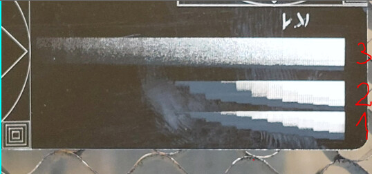
Then I set this image layer to Grayscale mode and run an engrave.
The result was very strange. (1) (2)
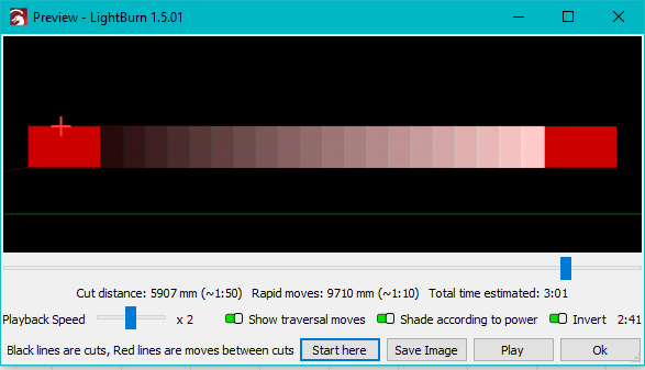
The preview seems OK.
I think it should be around even, but I see that it is changing from line to line.
Why is it so?
Then I changed to “Jarvis” and run it. The result was like the same (3).
It seems it changes the power more and more as the engraving goes forward in time.
The engraving is from a new Atomstack R30 V2 laser head on an Ikier K1 Ultra. (0.04interval is intended! torolni.lbrn2 (32,6 kB)
)
The machine’s X,Y axis working fine with the blue diode laser head.
Your DPI is too high. You’re likely getting overburning between lines which may be obfuscating results
I’m guessing your laser is either out of focus across the entire range of the material (ie surface level is uneven) or the material coating itself is inconsistent across the surface.
This is an AtomStack R30 V2 IR laser which has this super 0.02i resolution. So I think 0.04i is ok.
I will try the 0.1i to see if any difference.
The material surface is super flat and consistent. (85x55mm black painted aluminium)
I have tried to engrave a rectangle with “Fill” mode in Lightburn. It shows even engraving with very good result with 0.04i, so I have problem only with image.
I didn’t realize that the laser module was IR. I know the theoretical resolution is higher but not super familiar. If you haven’t already I’d suggest running some interval tests to make sure you’re getting the resolution that you expect.
Knowing now that it’s an IR laser I suspect this is really going to come down to focus. The effective focal depth of the laser is extremely narrow. Any variance in focus will likely result in quite a variation especially when you’re attempting to do something requiring a lot of finesse like grayscale or dithered images.
You can prove this out. Try refocusing at the opposite corner of the material from where you have been. Does that change the transition point of the burn?
This isn’t likely to be a comparable test given the nature of the burns.
Try this:
Create 21 rectangles that match the shape and size of each gray section of the grayscale image
Set all the rectangles to a single layer with Fill and match the interval size to what you have currently for the grayscale level.
Divide 0%-30% power into 21 evenly spaced power levels and assign each rectangle to one of the power levels. Go to shape properties for each shape and change the power scale such that each rectangle gets the appropriate power according to it’s assigned level you determined earlier.
As far as I can tell this should be as direct a comparison as possible using vectors vs raster data for the grayscale.