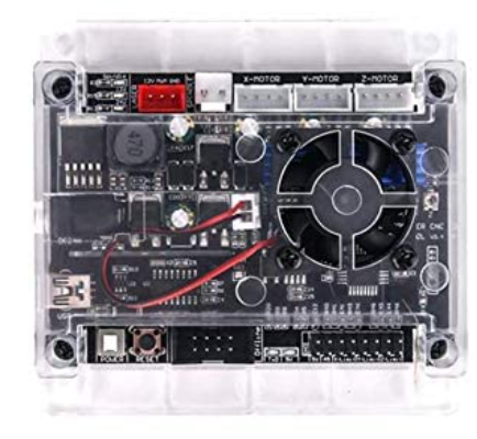
I have a GRBL 1.1f board and a china made 12v diode laser that I am trying to get up and running with lightburn (a very nice product I must say!). I have attached the image of the GRBL board. Its power supply input is capable of a range from 12v to 36V.
So here is my question: I have powered the board with a 12v 1a power brick and can fire the laser but feel that 1a is way under what i should be using with 3 steppers, the board and the laser. Without going into it, the laser will somewhat draw a line but only at 5mm/sec at say 80% power. So I was thinking its a laser focusing and supply issue. Does anyone know if these “woodpecker” style boards will still power the 12v laser if i switch the board to a 24v 6a supply input? I am wondering if the onboard buck converter (or whatever they are using to regulate the 12v output to the laser) isn’t really ment for that that. Thanks in advance.
I had thought that normally these boards required 24V input power. Spindle power is meant to be 24V and doubt they’d be upconverting voltage on the board. Do you have a meter to test the voltage on the spindle pins?
Even a single stepper could easily require 1A so yes, that power supply is dangerously underrated. I suggest you stop using it as it’s likely being overloaded. Is it excessively hot under operation?
Depending on the laser module you have… with 3 steppers you’re easily in the 12V 5A category but could go as high as 12V 7A. But I guess in reality you’d never be using the Z-axis at the same time as XY so you could potentially eliminate that motor from the equation.
I don’t have direct experience with these boards but from what I’m seeing in the woodpecker manual the expected input voltage is 24V.
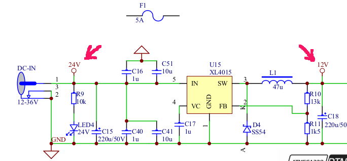
If input voltage is variable from 12V to 36V as you say, however, I don’t know where that leaves this. I suspect in that case that spindle voltage would be same as input voltage and that all other voltages would be halved, or possibly regulated to 12V.
In any case, I suggest you use a meter to test all your voltages in any case.
I know that @jkwilborn has a woodpecker board and may have already explored this so let’s see if he can contribute something here.
My first woodpecker came with and ran on a 24 volt 4A supply. A thought that there was the possibility of a short and the fuse may fail to ‘blow’, so I went to a 5A model.
The arrows point to the 24V and 12V taps.
Notice the 24V tap is actually whatever the supply voltage is, could be as low as 12V or as high as 36V. There is another regulator down the road for the 5V.
The last little CNC3018 I purchased, a Vevor, came with a 24V 5A supply. It is not a Woodpecker controller, unfortunately.
Here’s the complete Woodpecker schematic… It’s really a pdf file… rename it before you attempt to open it…
Thank you for the fast response. All very helpful information for sure.
Actually no, the 12V 1A supply never got hot under use but honestly I was just using it to get the design off the ground, trying to make just very simple cuts before moving to a more “solid” supply.
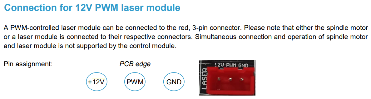
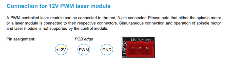
The one photo you supplied does bring me to my next question which may be the cause of much puzzlement for sure in getting my laser to work properly. I asked the vendor but didn’t get a reply. Perhaps you or someone can help with this also. You posted this image in your reply of the woodpecker connection:
Do you know if the image silk screening (12V PWM GRD) is the correct wiring option? I know on my laser module itself, it is 12V GRD PWM. I am wondering if I have (or what would occur) if I had these two reversed? I tried to research this question elsewhere on the web and never found a good answer. Yes, my laser is firing when requested to do so, but what effect would having the two backwards have? I feel like I am so close to getting it operational, and have gone thru all the Gerbl firmware settings after struggling with Marlin, getting no where, and moving to grbl…
Thank you thats what I thought. Also thank you for the schematic. It confirms the edge connection silkscreening is correct. Thank you for pointing me in the right direction
From what I’ve seen Marlin is less than ready for laser control and more importantly, well behind alternatives. It really only makes sense if you’re running a laser on an existing 3D printer.