GRBL-M3 to have settings like Marlin M3 & M5

Hi guys,

I am having a small issue.

I am using an Arduino + CNC shield loaded with GRBL to control a Pen Plotter.

Using an serial monitor I have set up my limits and settings.

My machine also raises the pen with M3 S90 (Laser Off)

Drop pen with M5. This is a physical limitation of my design of the machine.

Its there an easy way for me to adjust this like you can with Marlin.

I know this can work, all I need to do is swap M3 and M5 l.

I know this because I can save gcode, open gcode and use replace all then use run gcode and it works, however those becomes a bit tedious doing this manually.
In what way is M3 S90 laser off? Not following. M3 is spindle on. S90 is a non-zero speed.

M5 is spindle off.

When you say this is a physical limit can you elaborate?

Is there no way you can physically reverse the action of M3 and M5? What is the mechanism for pen actuation?

M3 S90

On GRBL for Arduino that uses a CNC shield with a micro switch connected to 5V and PWM on Z rotates 90 degrees CCW.

M3 S 180 would be turn micro servo 180 degrees CCW.

M5 returns to previous location. Which is 0 facing up.

It is a physical limitation because the micro servo is mounted a certain way pulling up my pen from touching my paper with M3S S90, and then releasing the pen with M5.
In my design there is no room for the arm to do a 90 degrees CW to release the arm, and M5 to pull up the arm, in an ideal situation that would be perfect.

There is an Inkscape extension called MI GRBL or jtp which does this but I just 5hoight using lightburn would be better, since it can connect to Arduino.

1 Like

Can you reverse the wires on the servo to reverse direction?

Right now there’s nothing in LightBurn that would allow you to swap M3 for M5 and vice versa. I understand there’s something in the works for a customizable g-code generator but no idea how flexible it will be or when it would come out.

I was playing with Lightburn and I do not get the correct result.
I also use an Arduino. I use the M3S180 for a pen up. When I look to the gcode I only get the M3. How can I force Lightburn that I get M3S180 in the gcode file.

Chris

Nothing you can do right now will force M3 S180 for pen up within LightBurn. If you can get M3 S180 to work for pen down then you could achieve this by:

  1. Set S Value Max in Edit->Device Settings to 180
  2. Set power in Cut to 100%
  3. Make sure you’re using GRBL-M3 device profile or use Constant Power mode in the Cut setting

If you do this, then you will get M3 S180 for power on and M5 for power off.

I use the grbl-m3 and this is not working.

Can you elborate what you mean by “not working”? What exactly is not working. What’s not happening as expected? What happens instead?

No, the Arduino controls the direction.

And I don’t have room to rotate 90 degrees clock wise, only CCW. Even if I could, I wouldnt be able to use M3, I would need to use M4.

GRBL gcode.h will explain all gcode commands.

2 suggestions for options:

  1. remount the servo rotated 180 degrees so that M3 S180 brings the pen down
  2. modify GRBL so that direction is reversed

[EDIT]
A third option is that you could create some circuitry to invert the PWM signal from the Arduino to reverse the direction of the servo.

You put it in the printers settings in the start gcode section.

You usually put:

M2
M3 S180
$H
G92 X0 Y0
M5

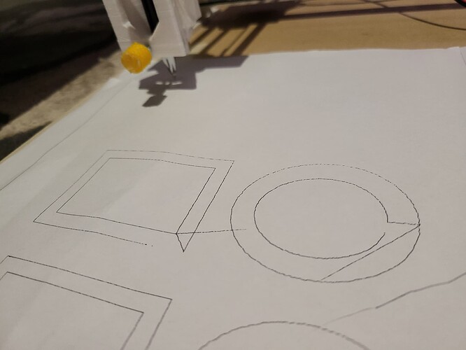
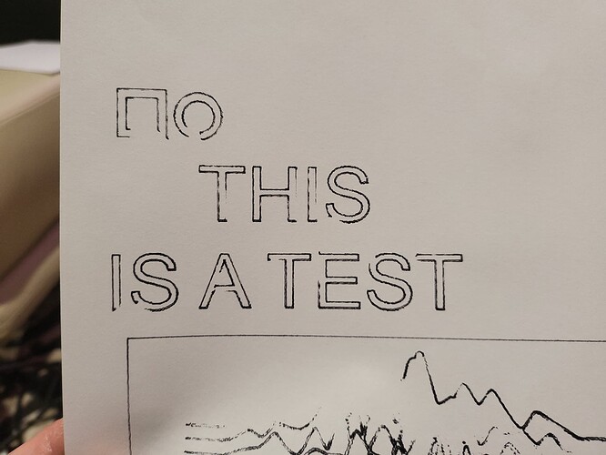
I ended up hot gluing the rotated servo 180 degrees, it works now kinda, the problem now is that it moves too fast before M3 or M5 commands finish lifting the pen so I get marks when the pen is still lifting and the plotter is moving to the next cut line.

Perhaps you’re one of the few folks around here who must turn Laser Mode off:

$32=0

Because you don’t have a laser:

I only get the M3 and not M3S180

Post the g-code that’s being generated.

You only need M3 S180 in the start up gcode once, all following M3 commands are the same until M2 is sent.

Start gcode
M2
M3 S90

M5

$H
G92 X0 Y0

End gcode
M5
M2

My GRBL does not have that as an available setting, my settings are:

$0=10 (step pulse, usec)

$1=25 (step idle delay, msec)

$2=0 (step port invert mask:00000000)

$3=0 (dir port invert mask:00000000)

$4=0 (step enable invert, bool)

$5=0 (limit pins invert, bool)

$6=0 (probe pin invert, bool)

$10=3 (status report mask:00000011)

$11=0.010 (junction deviation, mm)

$12=0.002 (arc tolerance, mm)

$13=0 (report inches, bool)

$20=1 (soft limits, bool)

$21=1 (hard limits, bool)

$22=1 (homing cycle, bool)

$23=3 (homing dir invert mask:00000011)

$24=500.000 (homing feed, mm/min)

$25=2000.000 (homing seek, mm/min)

$26=20 (homing debounce, msec)

$27=5.000 (homing pull-off, mm)

$100=4.880 (x, step/mm)

$101=4.880 (y, step/mm)

$102=360.000 (z, step/mm)

$110=50000.000 (x max rate, mm/min)

$111=50000.000 (y max rate, mm/min)

$112=5000.000 (z max rate, mm/min)

$120=500.000 (x accel, mm/sec^2)

$121=500.000 (y accel, mm/sec^2)

$122=250.000 (z accel, mm/sec^2)

$130=450.000 (x max travel, mm)

$131=350.000 (y max travel, mm)

$132=200.000 (z max travel, mm)

ok

$32=0

error: Invalid statement

This may not be so easy to remedy.

Some suggestions:

  1. optimize the pen position such that it doesn’t take much actuation to go from touching to non-touching states.
  2. reduce the rotation amount required to go from touching to non-touching.
  3. reduce acceleration and speed to minimize the amount of drag time
  4. move to something with faster actuation like a solenoid

Or just revert to manually altering the g-code and adding a delay after each M5.

Thanks for the suggestions, I am getting close!

1 Like

If you have to draw two separate square the pen have to lift up between the squares