Greyscale looks like just Black/white

I tried my first photo. I have a 3.5W laser diode. I selected greyscale , 200 dpi, 4000 mm/min and 100% power. I can see that the laser is on all the time, but I basically get a binary image, either black or no! burn at all. I know the laser works with PWM, I tested it when I first got it with a small PWM generator.
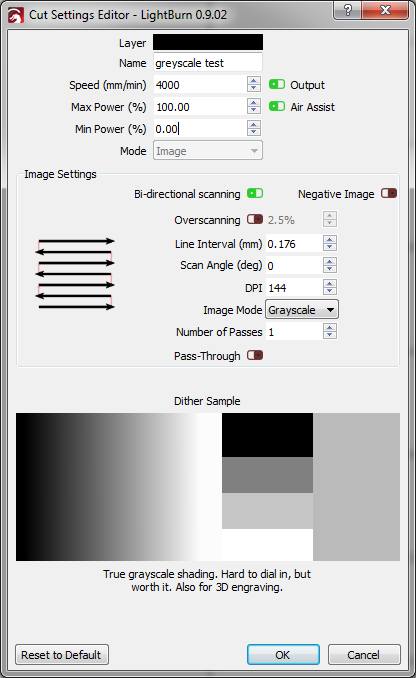
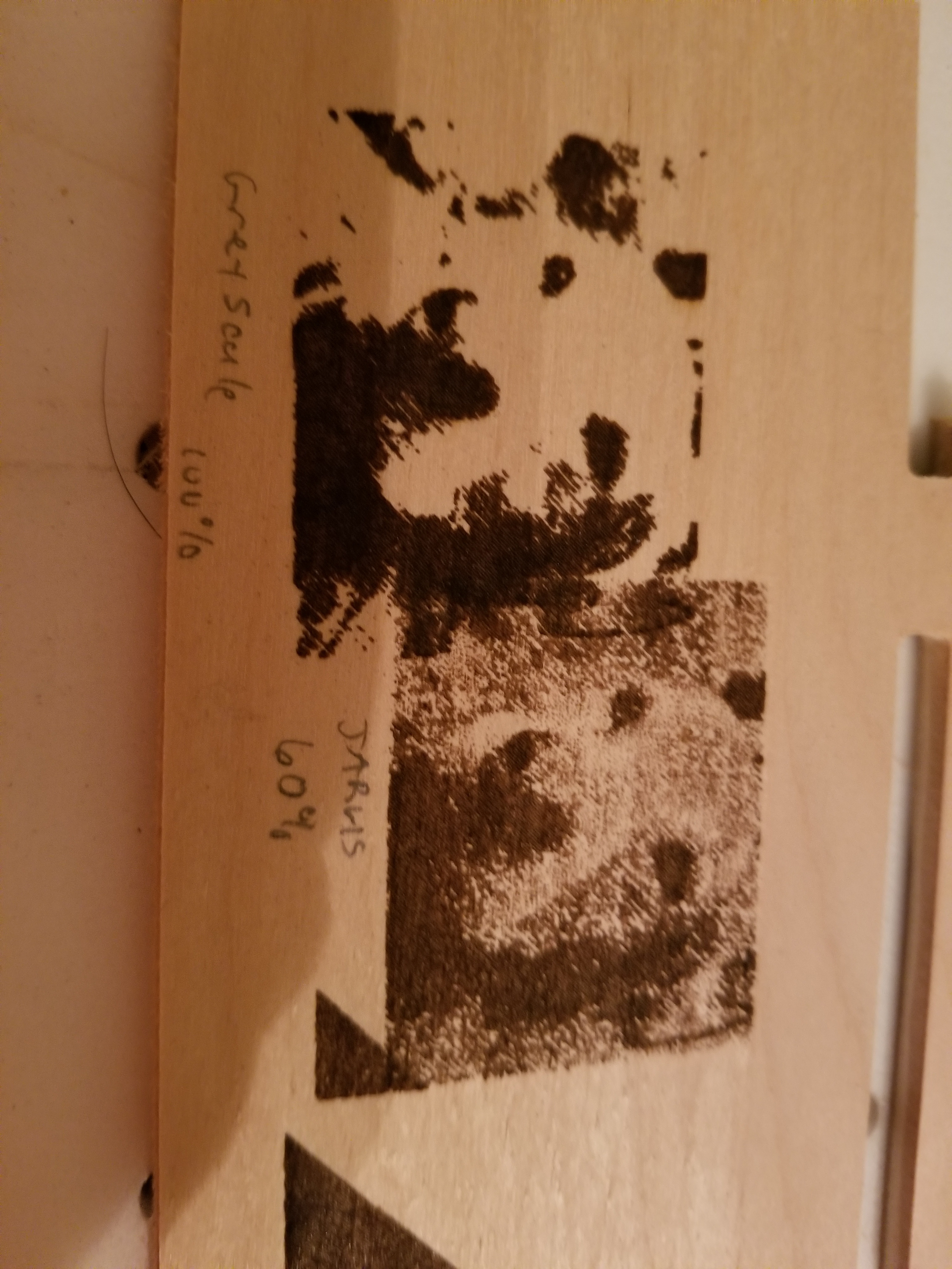
I also tried it Jarvis, and it looks a little better but still bad. But my first question is on the greyscale, do I have something set up wrong? This is on plywood.
Thanks

$0=10 (Step pulse time, microseconds)
$1=250 (Step idle delay, milliseconds)
$2=0 (Step pulse invert, mask)
$3=1 (Step direction invert, mask)
$4=0 (Invert step enable pin, boolean)
$5=0 (Invert limit pins, boolean)
$6=0 (Invert probe pin, boolean)
$10=19 (Status report options, mask)
$11=0.010 (Junction deviation, millimeters)
$12=0.002 (Arc tolerance, millimeters)
$13=1 (Report in inches, boolean)
$20=1 (Soft limits enable, boolean)
$21=0 (Hard limits enable, boolean)
$22=1 (Homing cycle enable, boolean)
$23=0 (Homing direction invert, mask)
$24=50.000 (Homing locate feed rate, mm/min)
$25=250.000 (Homing search seek rate, mm/min)
$26=250 (Homing switch debounce delay, milliseconds)
$27=4.000 (Homing switch pull-off distance, millimeters)
$30=1000 (Maximum spindle speed, RPM)
$31=0 (Minimum spindle speed, RPM)
$32=1 (Laser-mode enable, boolean)
$100=53.440 (X-axis travel resolution, step/mm)
$101=53.440 (Y-axis travel resolution, step/mm)
$102=397.870 (Z-axis travel resolution, step/mm)
$110=4000.000 (X-axis maximum rate, mm/min)
$111=4000.000 (Y-axis maximum rate, mm/min)
$112=500.000 (Z-axis maximum rate, mm/min)
$120=100.000 (X-axis acceleration, mm/sec^2)
$121=100.000 (Y-axis acceleration, mm/sec^2)
$122=10.000 (Z-axis acceleration, mm/sec^2)
$130=665.000 (X-axis maximum travel, millimeters)
$131=1270.000 (Y-axis maximum travel, millimeters)
$132=70.000 (Z-axis maximum travel, millimeters)

I suspect you’re quite out of focus - I can easily see the diagonal lines in the image without zooming in.

For starters, go to the Device Settings and turn on “Enable Laser Fire Button” then re-run LightBurn. On the “Move” window you’ll see a “Fire Laser” button with a power value next to it. Press the button and then slowly raise the power until you can see the light from the laser on your material. Adjust the focus ring on the laser (if it has one) or adjust the height of the laser above the material until you get the smallest spot you can.

Once you’ve done that, try running the image again.

I focused as best I could, damn it’s hard to tell how much its changing.

then i propped up a popsicle stick at an angle and set the laser height so it was focused at about the middle. I burned a line. The line looks much thinner than i had before, but it doesn’t look like it changes much for most of the line. I have no idea how thin the line should be. How does it look?

The flatter the stick the longer will be the narrowest marking. Pick the middle and measure up to your head.

If your table moves up and down it is easy to adjust Z in increments and burn spots. Look for the smallest one and measure up to your nozzle or read your Z location on the Move Tab. Use that as an offset in future setups OR cut a wooden gauge that is that distance.

I used a set of calipers and a microscope to measure the width of a cut. It is about 0.18mm wide. How thin should i be able to get it?

I tried an image for a greyscale test.

The blocks get smaller, but not lighter. then they just quit. Any ideas on what could be wrong?

Your profile identifies you are using a grbl controller, but we need to know a bit more to be of help. What version of grbl are you using and what are the current firmware settings? Type $$ into the LightBurn console and copy and paste the results here and we can go from there.

Additionally, please provide a screen capture (no cell phone pix) of the LightBurn Layer settings (‘Cut Settings Editor’ window). Double-click the layer to expose that window.

GRBL 1.1f
$0=10
$1=250
$2=0
$3=1
$4=0
$5=0
$6=0
$10=19
$11=0.010
$12=0.002
$13=1
$20=1
$21=0
$22=1
$23=0
$24=50.000
$25=250.000
$26=250
$27=4.000
$30=1000
$31=0
$32=1
$100=53.440
$101=53.440
$102=397.870
$110=4000.000
$111=4000.000
$112=500.000
$120=100.000
$121=100.000
$122=10.000
$130=665.000
$131=1270.000
$132=70.000

The picture you showed is scanned at an angle, but the settings you posted don’t reflect that. Assuming that’s the only difference, I don’t see anything wrong.

What kind of diode do you have, and how is it wired? It’s quite possible the diode itself is just thresholding on/off instead of accepting PWM.

This topic was automatically closed 14 days after the last reply. New replies are no longer allowed.