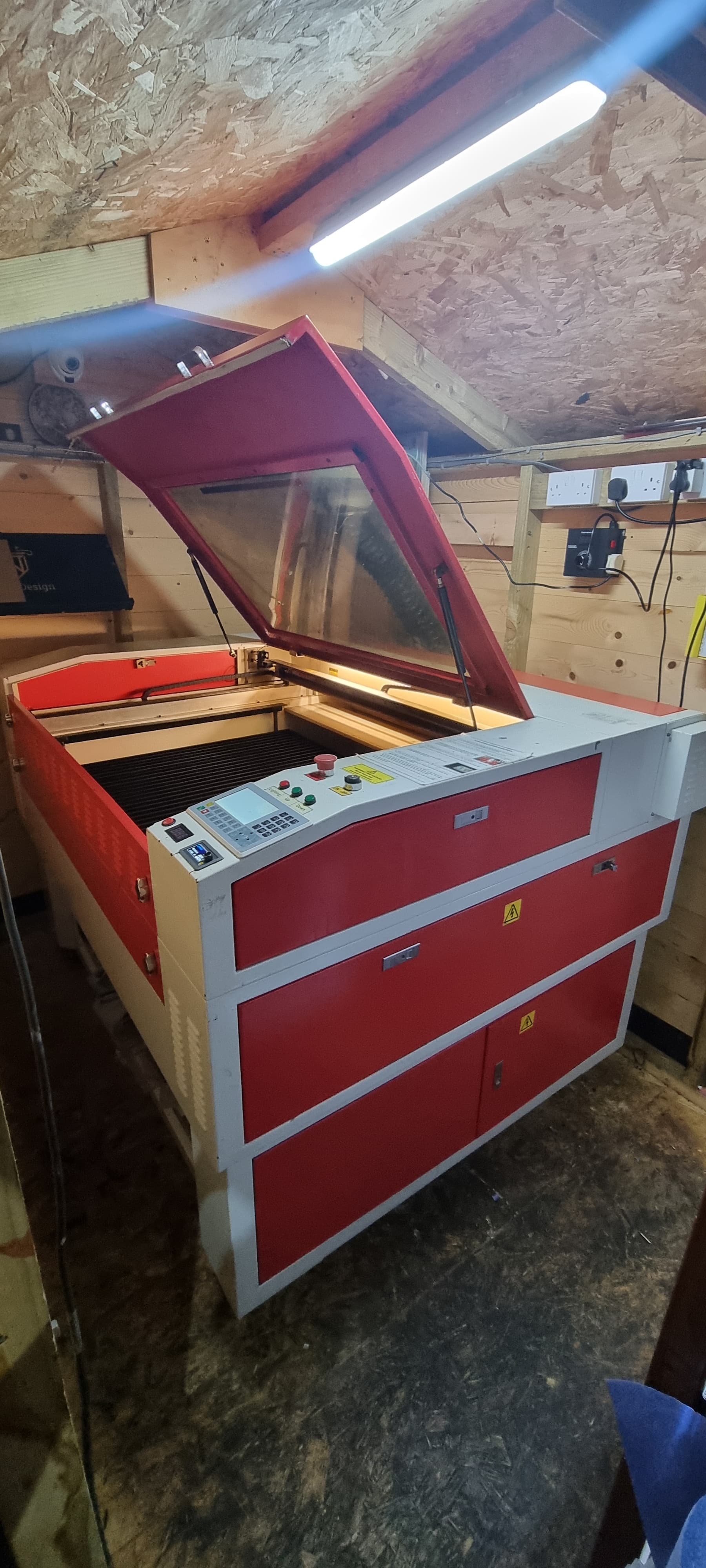
Hello all, I have a HPC LS1290 which I have retrofitted a Ruida RDC6445 to last year. It’s been running fine ish with the usual random issues but this is one that has completely baffled me and I’m hoping someone may be able to help.
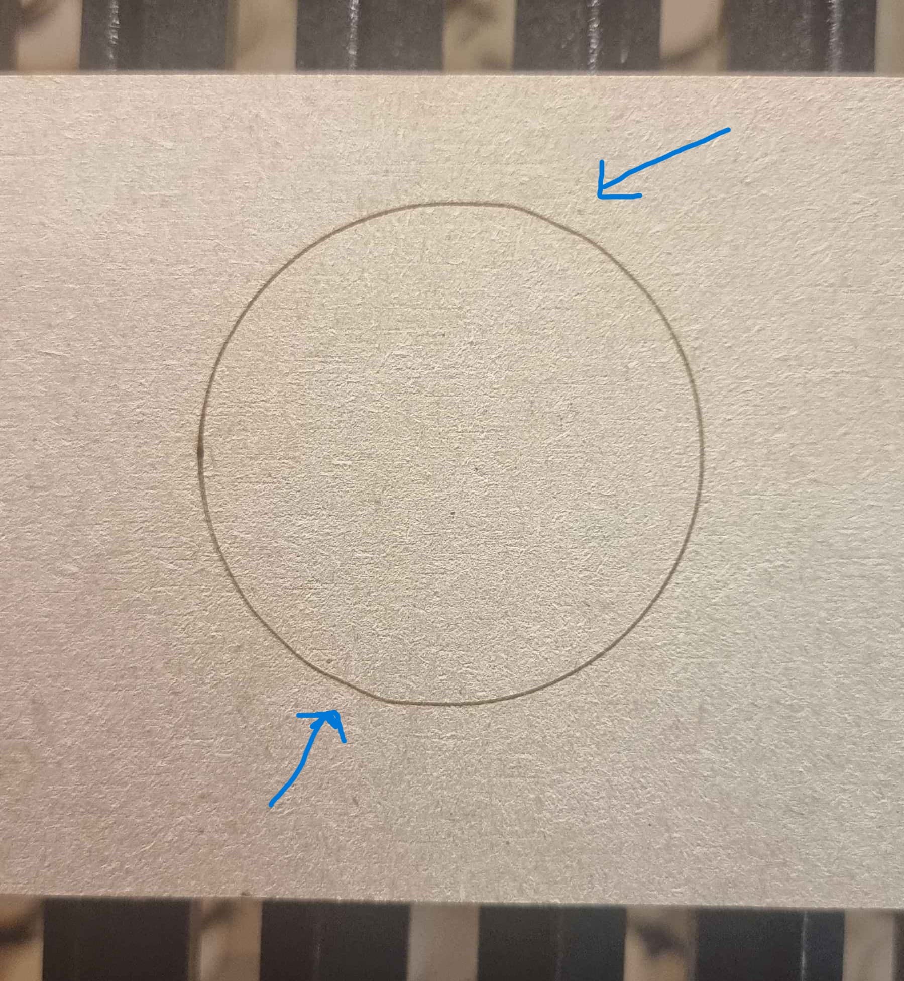
I re-alligned my mirrors the other day after fitting new ones + lens because i accidentally bumped the 2nd mirror and it cracked my focus lens and from there on It just seems have had an issue with these artifacts when cutting/engraving curves. Squares etc no issue on them.
Things i’ve tried so far to fix the issue or troubleshoot.
1 - Changed all bearings on the idlers for the belts
2 - Retensioned and slackend belts to check for difference
3 - Made sure all mirror mounts are tight
4 - Made sure tube is tight held on its brackets
5 - Made sure the laser head carriage itself is tight and no slop
6 - Cleaned the pulley teeth on the steppers as they had some gunk in them
7 - Checked for play on the pulleys themselves
8 - Flipped connections to the steppers x/y on each drive it continues to do the same so flipped back to original connections
9 - Reduced accelerations on X and Y to 1000 mm/s from 3000
10 - Checked steps and both X and Y are correct for distance told to move over a 800mm span.
Laser cutter for reference so you can see what it looks like and how its made in case this is a factor
I forgot to mention that I have done the same test with a circle in all four corners of the bed with the same result, done the test at 10mm/s and then 400mm/s with the same result no significant change to the deviations seen in the image.
This looks like a mechanical issue. I’d say, from the looks, it’s an X axes problem. Most of the Y movement looks good, just the transitioning to X causes issues.
Might check grub screws on the X axes (both wouldn’t hurt) pulley and/or change the tension on the X belt to see if that helps.
It appears as backlash to me, not a controller/software issue.
Good luck – these are the most challenging type of problems.
That may be because the errors are less obvious when only one axis is moving.
That much of an impact surely overstressed the laser head mounts, perhaps to the extent of wrecking the screw threads in either the (steel?) belt attachment or the (aluminum?) head.
Jog the head to somewhere convenient, then grab the focus tube and wiggle it back-and-forth while feeling for any looseness. It may be in the tube mount, the belt anchors, the linear bearings, or anywhere at all.
With the power on, you should not be able to move anything in the laser head at all while applying more force than you think you should. If you can feel anything, then you’re looking for the two parts that move relative to each other.
It would have to jump back a tooth. If it were this issue the rest of the object would be off one tooth each time it occurred and I think you’d see it.
I have checked over all movement points and ensured every single bolt and grub is tight. The X axis ones don’t line upto the flat spots on the long rod which joins both so they are currently just nipped up against the round surface otherwise the gantry isn’t square if they are lined up on the flat spots. Do you think they may be slipping even if they are tight on the surface?
I’ve changed the tensions on X to very slack, normal and tight with no change to the issue.
Regarding backlash, does lightburn have a backlack compensation?
When I say bumped I mean I knocked it with my elbow which moved the beam slightly askew and resulted in it cracking my focus lens as it was right on the edge and melted the silicone washer. There wasn’t any force involved to the mechanisms just my clumsy elbow on the 2nd mirror mount.
I just realised I’m replying in relation to the Y axis, ignore the previous. So the X axis belt has no grub screws or anything along those lines. The belt is bolted on at each end to the laser head and the stepper timing pulley is press fit on to it.
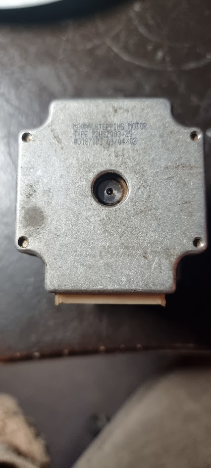
I did wonder if it was stepper related as its just a regular Nema 23 by all accounts.
Precisely,… my bad english… thank you for the correction.
Then, if I don’t tell you don’t guess. Sorry.
My machine as two Y axis stepper motors and end switches only on one side (i don’t know if it used mounted switches for both steppers) , so it jump a tooth on one of the belts and homing does not solve the problem.
I had to loose both belts, square the machine and re tight the belts again.
With English being a second language for you, you’re doing well. So hang in there and comment when you think you can add something to the conversation.
I can easily enough replace the stepper, finding a close to match timing pulley is proving difficult though. The existing one is 25T and the belt is 16mm wide
Whenever I have form inaccuracies the first place to look is the Y axis stepper and shaft. You can check it by grabbing one pulley and seeing if there is any play (angular play) between pulleys. Not sure how to check that if you’re using two Y axis steppers. If that checks then I go to belts and belt alignment on pulleys. It’s usually mechanical.
As everything everyone has mentioned so far has been fine to what I can tell I’ve ordered a new 23 stepper and pulley. Will need to recalibrate the steps as the only one that wasnt a 3 week wait was a 20T one.
Hello all, so I have been waiting on parts which have now been fitted.
Fitted new belts, new pulley on the Y new stepper on the Y, near bearings on the Y idler, new carriages on the X axis as they where sounding a bit gritty.
Tested it again today and the issues are even more prominant than before. The circle ends are now not lining back up when it comes around.
I’m pulling my hair out now, can these replacements maybe now narrow down what the issue may be?
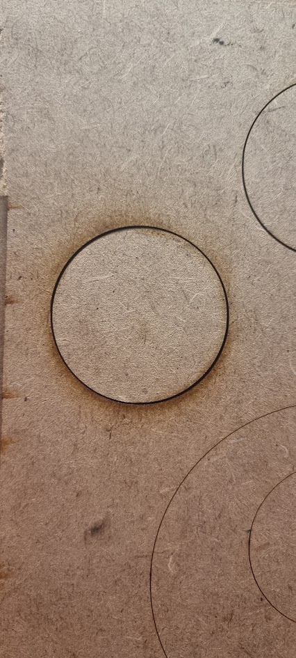
I’ve gone ahead and tried 0.5mm and 0.25mm on the Y. The 0.25mm seems to look the better so ive just stayed with that for the time being. There still seems to be the issue with the none concentric circles though.
So here you can see, i have rotated the cut part 90 degrees and you can clearly see its tight on the two edges and the other two 90 degrees apart are significantly larger. Measurements wise for a 50mm circle its cutting 49.81 and then 49.47. I’ve re-chjecked the steps and they are bang on for a 800mm length cut.
The point was to not have the controller compensating for the backlash, because fixing the mechanical issues is the only way it will actually work.
If you calibrated the step length on a cut piece, then the measurement includes the kerf width and will be incorrect for any other length. In particular, smaller distances will come out much smaller due to the more-or-less constant kerf width.
Set the machine to mark (not cut) cardboard or paper, draw a rectangle as large as the platform will easily accommodate (say 1000×800 mm), measure the center-to-center distances between opposite sides, and correct the step length to suit.
With that done, draw 50 and 100 mm squares with the power set to mark (not cut) and see if the situation improves.
It is entirely possible the beam is not circular and the kerf is not symmetric, so measuring cuts will not produce the right answers.