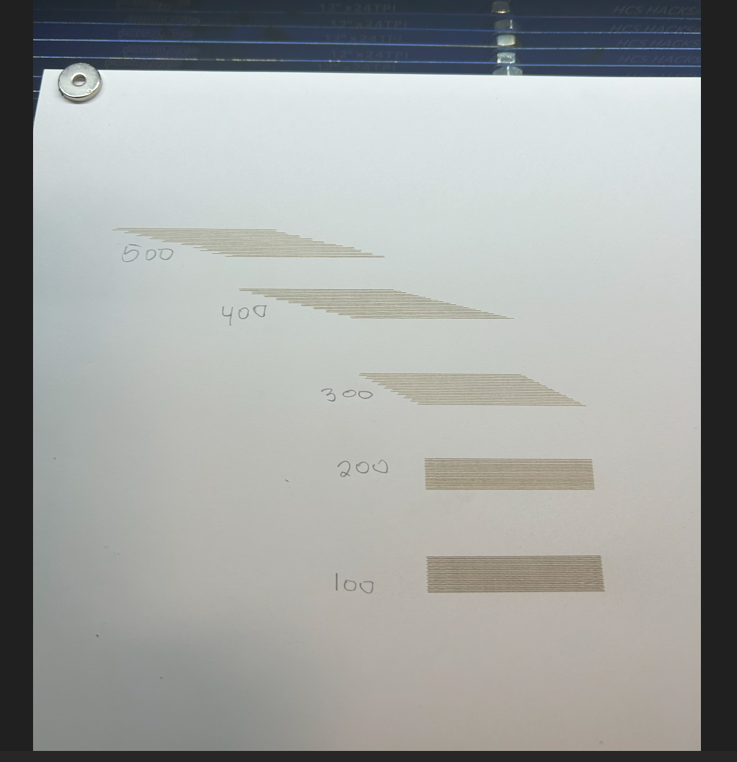
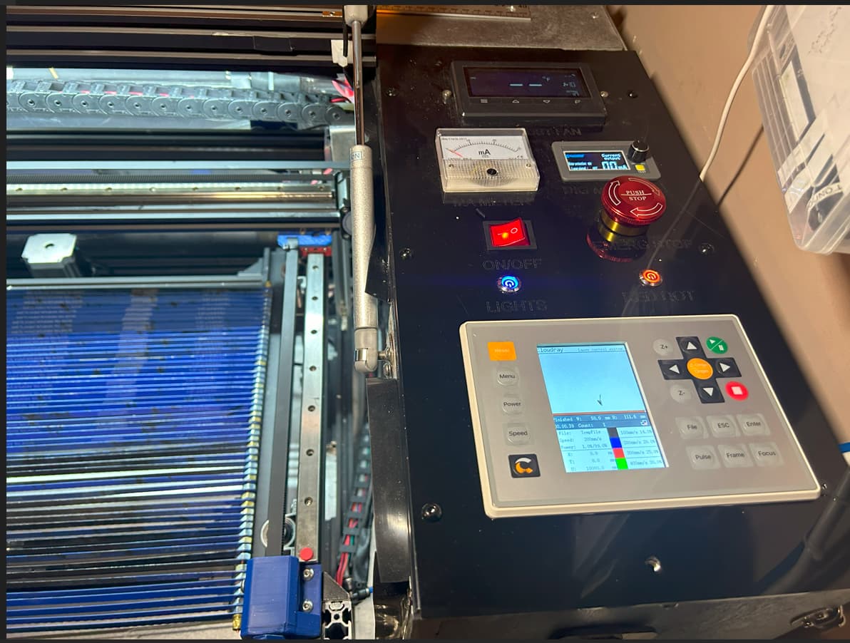
ruida 6432G, homes perfectly, yet when I run this backlash test I get this bad left shift once it starts the 300 mm/s run. and after it finishes it slams into the x axis homing switch. I did calibrate both axis , and Im at a loss on how to correct this ? any remedies
Looks like the acceleration values are too high and it’s losing steps…
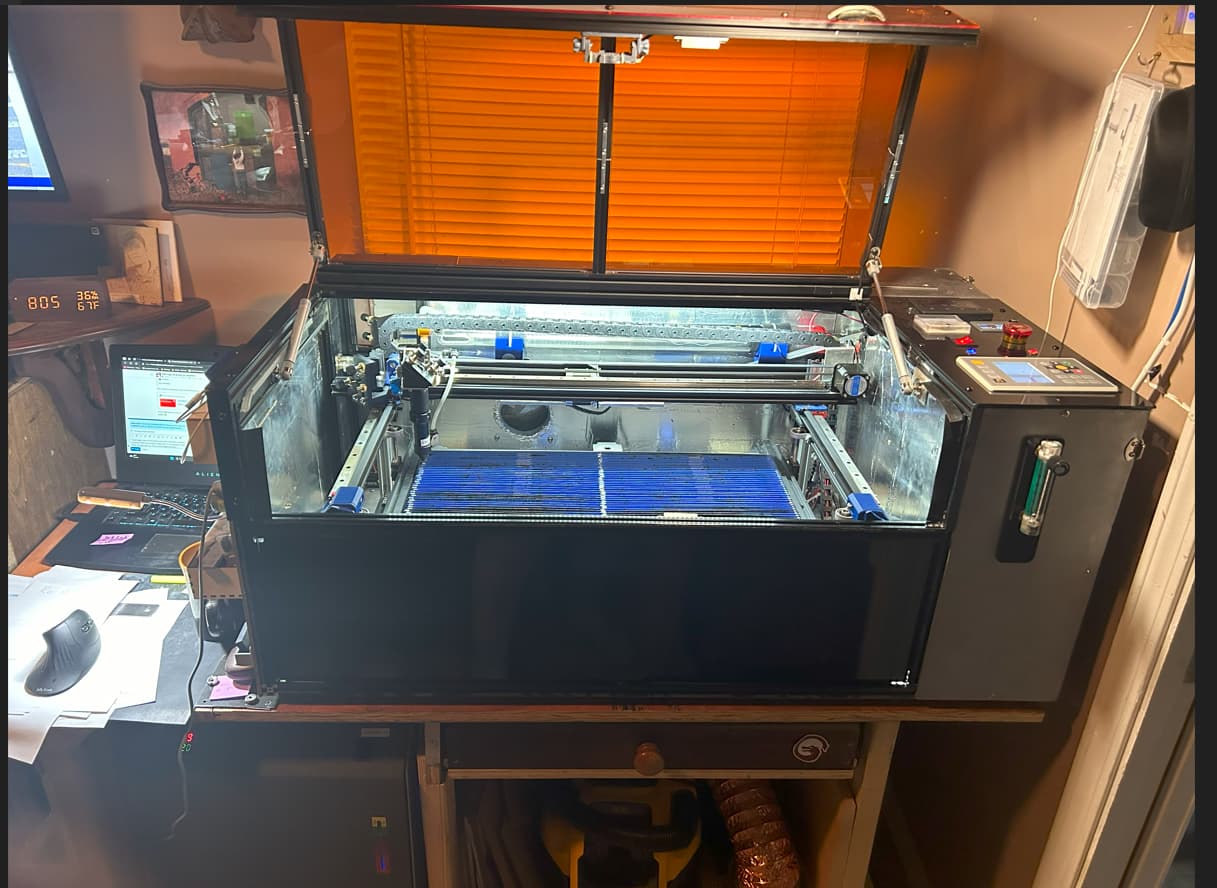
What kind of machine is this and what are the acceleration values for the X axes?
Your profile says a 3018 type… did you upgrade?
Is this a new machine or?
![]()
The machine configuration may have the wrong polarity for the X axis STEP pulse:
Your profile says you have a 3018 running GRBL. If you’ve upped your collection, brag on them in your profile. ![]()
1 Like
2 years ago it was a 3018 diode a year later a k40 then a modified 12 x 24 jambed in a mini k40 enclosure which was actually smaller than 12 x 24 because I went to cloudray c series mirrors and head. now its a real 12 x 24 in a much bigger enclosure . I changed some things like y axis to nema 23 dual shaft but kept nema 17 on x axis from past machine. I could run these scan offsets in past from 100 thru 500 mm/s and never had this problem. I will check out your reply and get back to yoy. thanks
went thru all the combinations, and the ones I had set worked best. one thing that seamed to help for a while was changing the microstep switches on the driver , it made the backlash test results better but other problems were still there ???
Given that the errors get progressively worse at higher speeds and are very large, suspicion falls on the X axis drive train. If the motor pulley has a setscrew, make sure it’s snug on the middle of the shaft flat.
I assume you are also changing the Ruida’s mm/step (or µm/step) values to correspond with the new driver settings. You must do that for each switch change to have the controller move the axis the correct distance at the proper speed.
yes jack , I will check into the acceleration speeds for X axis and try lowering them
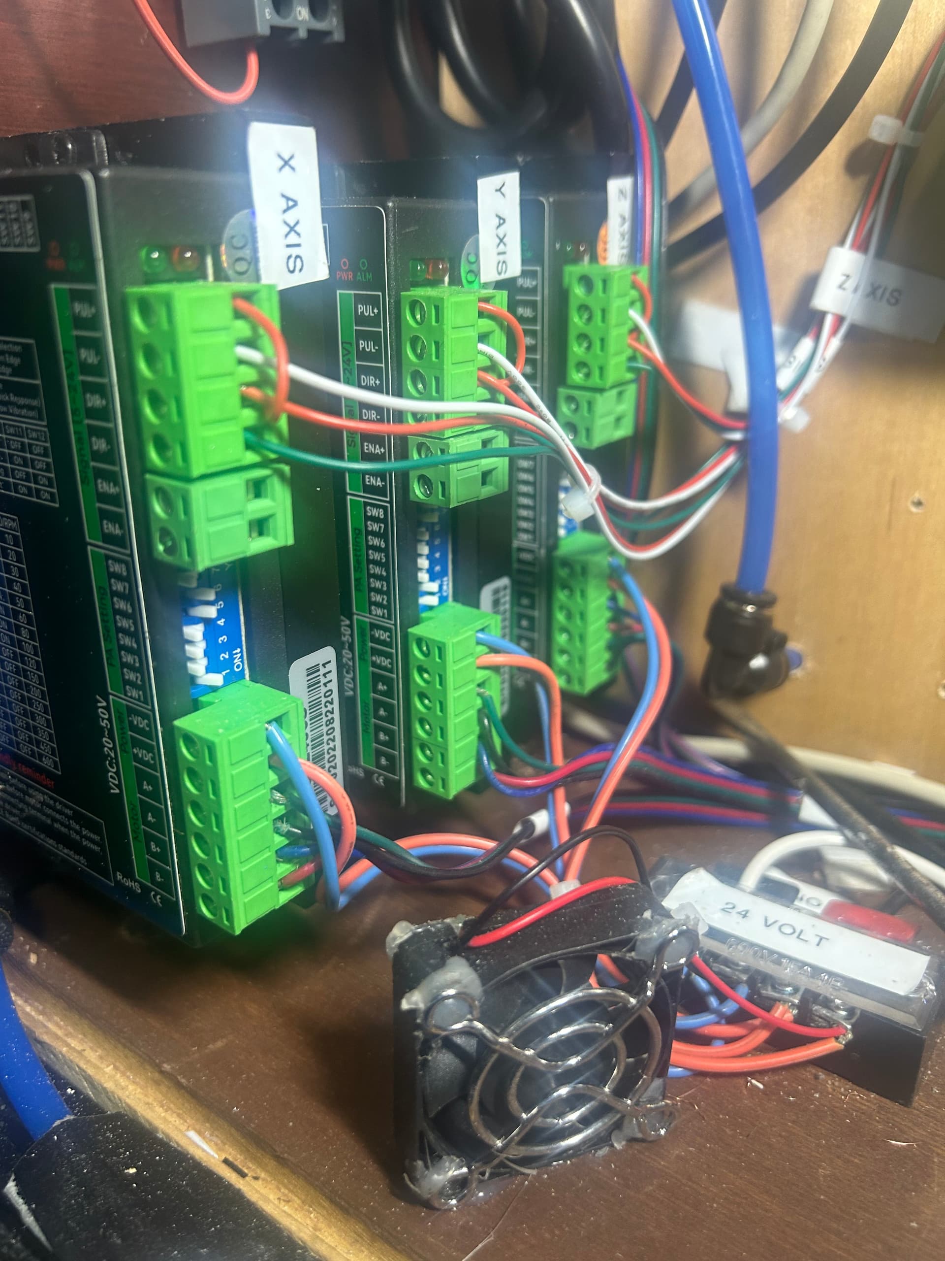
Well I have spent two weeks trying to figure this out since transferring everything fro ould to new machine with no luck, until today !! So I decided to dismantle the x axis from the motor all the way back to the stepper driver , andlo and behold what I found ! the Little red jumper wire which joins the other red wire looked like it was secure but when I checked it ,it never was clamped down in the connecter ! it was acting kind of normal a slow speeds be as speeds got higher it must have been making and breaking which is why it was loosing steps and then crashing into the origin after running the job ! secured that wire and sure as heck, that was the problem. Thanks guys for your help, it was driving me crazy ! just goes to show what a little screw up can do.
Congrats on the find…
There is nothing worse or more difficult than finding an intermittent connection…
The Chinese machines have a line of glue stick dribbled on the connectors to help secure them. I’ve found, as others have, that the screw wasn’t screwed down, the glue is what was holding it…
Have fun…
![]()
this is a home built machine, the chinese only supplied the building material, and the connection problem probably has something to do with whats called a senior moment ! In this case I did’nt check and recheck, and also I ASSUMED I had done it right the first time ! Makes me laugh at myself especially aftger spending two weeks thinking There was a calibration , or who knows what other problem. Well not so much. But a learning experience nun the less>
Had same problem with my rdc6432g. Now runs perfectly. File-> device settings-> enable scanning offset adjustment. Than create file for engraving squares with different speed and messure offset and create chart. Make few tests until perfect.
My k40 engraves at speed 500 and 30kmm/s2
Is this the actual acceleration value you’re using?
![]()
Yes. 30000mm/s2
I was unaware they these could handle that kind of acceleration.
Mine, with work is 45kmm/s^2. It will also run 1650mm/s confirmed. Great fun, but not practical.
![]()
For K40 laser it’s limit 500mm/s and that accelaration on X.
I’m at the moment designing new co2 laser with AC servos, it shoud run at much higher speeds and accelaration of 70000-100000mm/s2.
Here is video

The real advantage of a higher acceleration values is a much smaller overscan. The real limitation is the lps.
Using preview, you can see the overscan and it’s effect for a 40K value compared to a 6K acceleration value. Notice the difference in job time. It spends less time in overscan, more time doing the work.
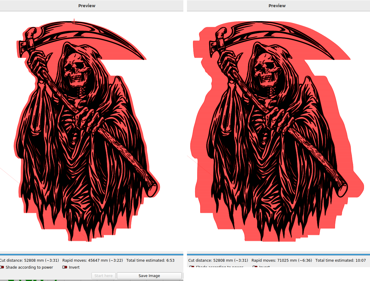
At 40k there is little overscan. Are you going to profit much eliminating that small amount of overscan?
If you take a typical K40 where the pwm is used to enable the lps, this input is specified to respond <=0.10ms. So at 1000mm/s the best dpi you can expect with a 0.10ms response time, is 25.4 dpi. You can only turn it on or off for each mm of movement or 25.4 times an inch.
If you slow it down to 500mm/s, still within the response time of the lps, the best is only 50.8 dpi. 250mm/s gives you 101.6 dpi.
Simply put, the head is moving faster than the response time of the lps…
A much quicker and costly modification is probably an RF module. It has a much faster response time, I’m told.
Even correctly configure and driven lps, such as a dsp has the same limitations for anything that needs that needs it to toggle between on and off.
Fascinating build… Love to see it, but wonder if it’s really useful for much other than academic interest.
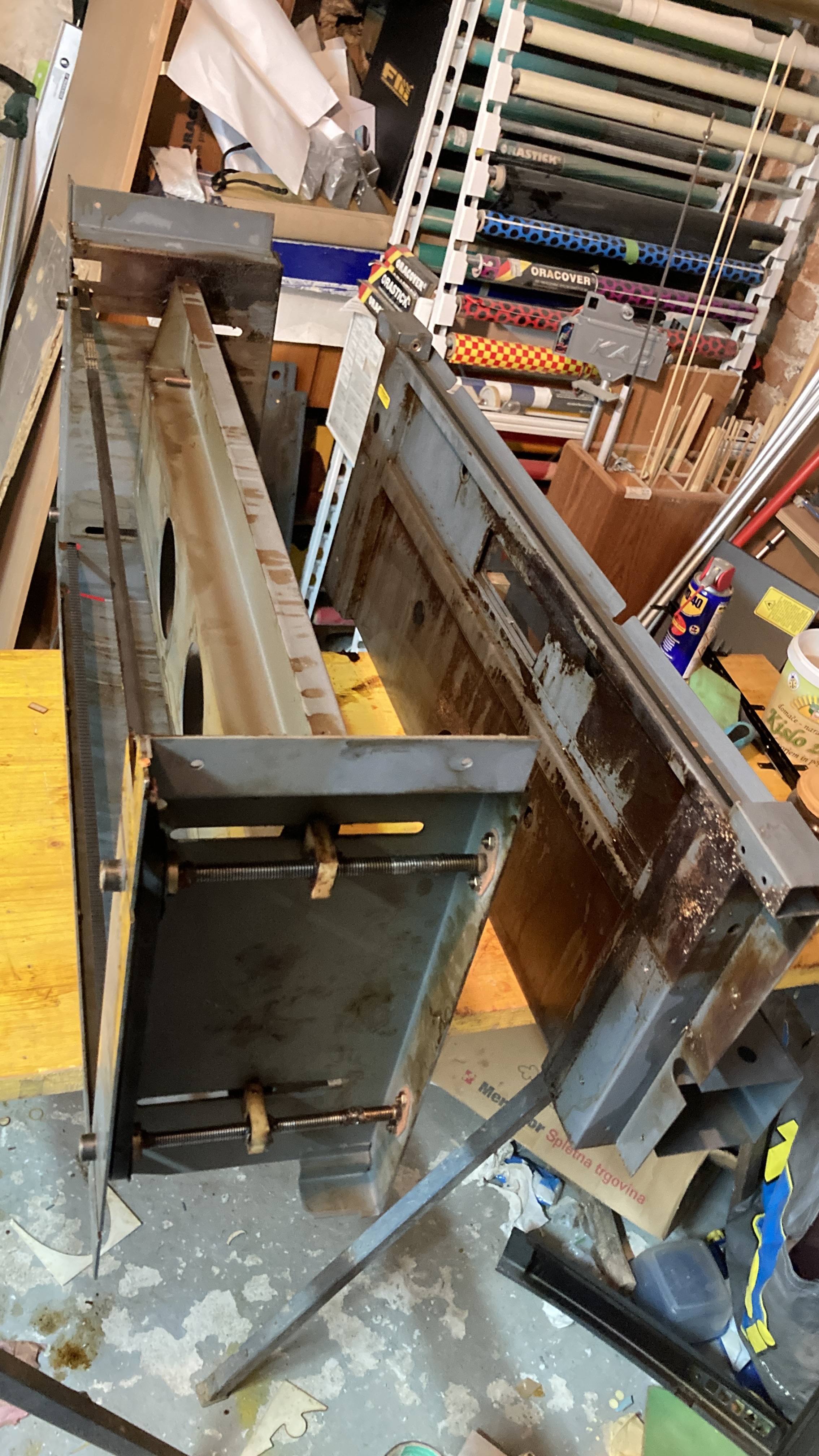
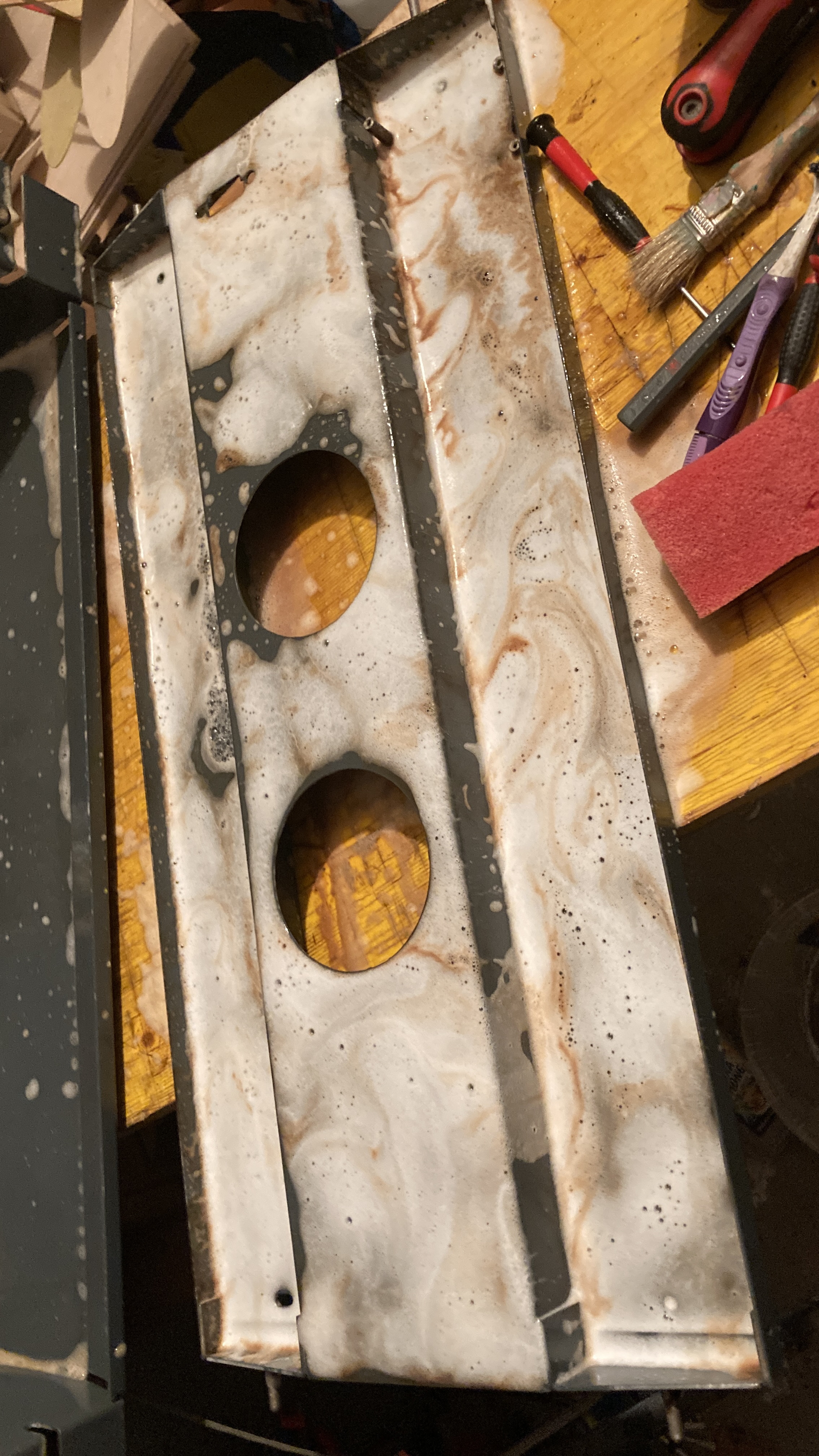
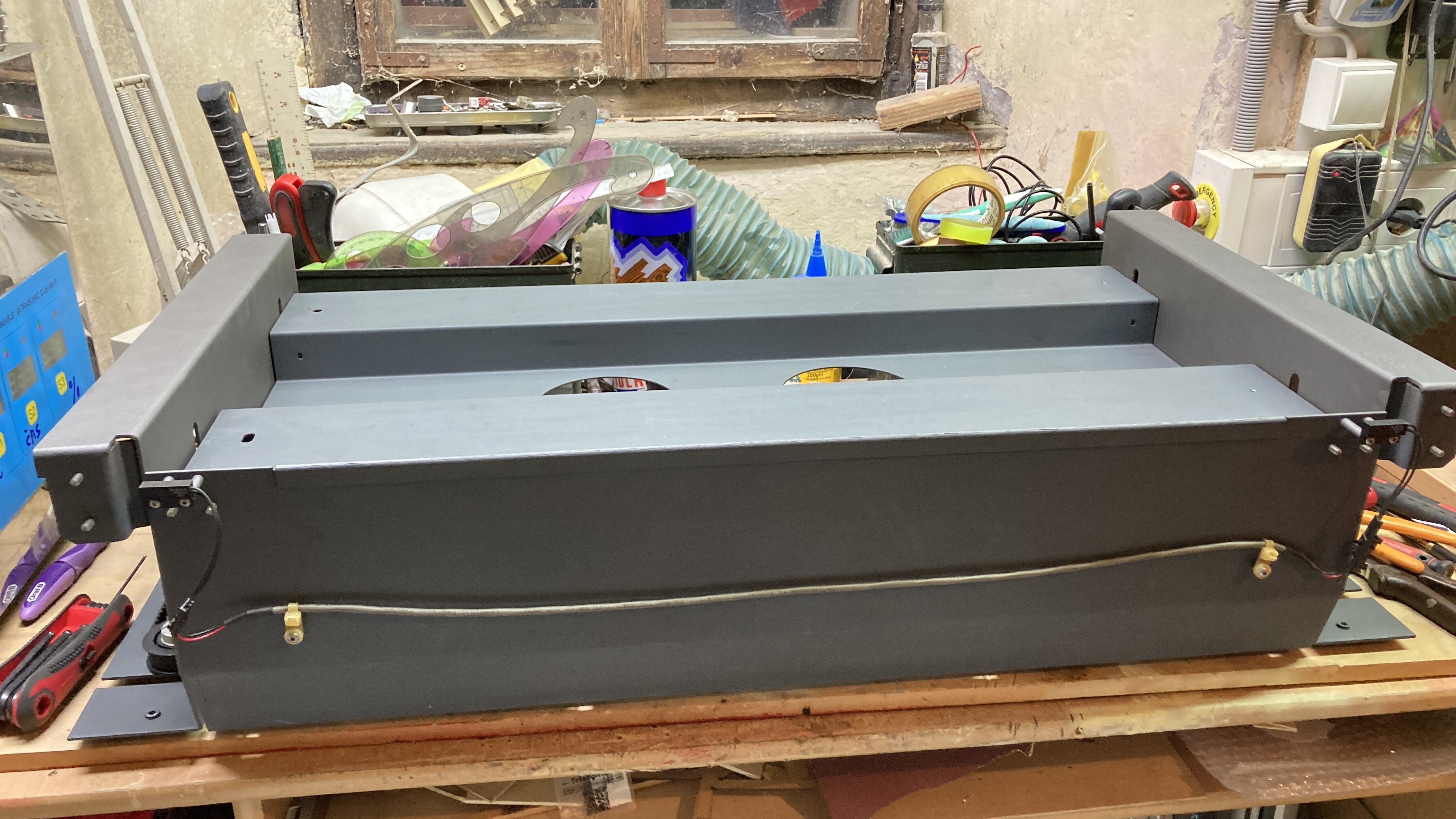
Please post photos of the build… many of us really enjoy the diy end of things…
Good luck
![]()
1 Like
RF tube is something out of my budget.
But I like DIY buils, specially when I design my own stuff.
I got from my friend 20 years old Universal laser VL-300 with 50W RF tube in bad shape ( it took me twoo weeks to clean it), now I’m putting it together. Only problem with machine is, that tube is almost dead and they want 3000-3500€ for refurbish it.

Seems excessive for just a re-gas of the tube… One of these sites stated their 80W was about 1500 bucks for a re-gas… Still expensive, but it would be the best for a faster machine…
Thanks for the photos… always love them and people who build them…
Good luck - take care
![]()
1 Like
This topic was automatically closed 30 days after the last reply. New replies are no longer allowed.