Hi Everyone,
This week-end I have designed and 3D printed parts to install a camera on my laser head and I did a lot of tests…
Now, I would like to share with those who are interested my findings while using the calibration process for a head mounted camera. I finally understood how the wizard is working and I can use it now in a consistent way (after reading some posts and many trial/error loops).
This feature is still experimental and I reported in a document the procedure I am following in a very detailed way and some findings for LB team…
But unfortunately, we cannot attached a pdf file in a post. Is there any alternative solution for this ? My document is a combination between an user manual with many screenshots and a bug report… I will be difficult to slice it… I have 33 pages !!
My conclusion is that:
- once you understood how to use it, you can create an picture of your work area
- My cuts are not aligned with the overlay, there is a bit of misalignment. Not that much…
- The “Update overlay” button is a real pain and needs a confirmation window before starting the stitching process
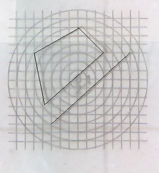
The picture attached is showing the overlay and the cut drawings (a line and a polygon shape) with the misalignment
On a side note: I built a set-up to use the head mount camera with a crosshair reticle. I will open another topic to discuss about this…