I have just started with a new Sculpfun S9 machine and installed bothe Laser GRBL and Lightburn. I added limit switches and made the setting offered on several youtube videos/ The head moves in the right direction. On starting Lightburn the machine tries to do Homing but. while the red lights on the switches light up, the switches do not stop the movements. a message appears: ALARM:9
Homing fail. Could not find limit switch within search distance. Defined as 1.5 * max_travel on search and 5 * pulloff on locate phases.
ok
Ortur Laser Master 2 Ready!
OLF 140.
Grbl 1.1h [’$’ for help]
[MSG:Check Limits]
[MSG:’$H’|’$X’ to unlock]
[MSG:Caution: Unlocked]
ok
Could anyone please help solving this issue? Thanks
You mention that this is for a Sculpfun S9 yet the console output is from an Ortur LM2. Can you explain the discrepancy and provide more details on what’s going on?
How have you sourced the limit switches. What switches are they? How have you connected the switches to the controller?
Hello and thank you for relating to my problem. My machine is a Sculpfun S9. I have no other machine and I do not understand where the mention of Ortur came from. I tried again now and this is the text of the alarm: " Homing
ALARM:9
Homing fail. Could not find limit switch within search distance. Defined as 1.5 * max_travel on search and 5 * pulloff on locate phases.
ok
Grbl 1.1h [’$’ for help]
[MSG:’$H’|’$X’ to unlock]
[MSG:Caution: Unlocked]
ok". I do not understand this alarm message. Could you help to fix the problem? Thank you
If the limit switches are not stopping the laser that means either the switches aren’t working or the controller is not responding properly to the switch.
I’m not convinced that this situation with Ortur has gone away.
The Sculpfun S9 is not configured to home. Did you enable homing?
Hello. Yes, I have configured LB: auto-home on startup and, indeed, it starts the homing but then the switches light up but the machine does not stop.
The printout of the commands you asked me to write is:
“ok
$$
$0=10
$1=25
$2=0
$3=0
$4=0
$5=0
$6=0
$10=1
$11=0.010
$12=0.002
$13=0
$20=0
$21=1
$22=1
$23=2
$24=100.000
$25=1500.000
$26=250
$27=3.000
$30=1000
$31=0
$32=1
$100=80.000
$101=80.000
$102=250.000
$110=6000.000
$111=6000.000
$112=1000.000
$120=1000.000
$121=1000.000
$122=1000.000
$130=410.000
$131=400.000
$132=200.000
ok
$#
[G54:0.000,0.000,0.000]
[G55:0.000,0.000,0.000]
[G56:0.000,0.000,0.000]
[G57:0.000,0.000,0.000]
[G58:0.000,0.000,0.000]
[G59:0.000,0.000,0.000]
[G28:0.000,0.000,0.000]
[G30:0.000,0.000,0.000]
[G92:0.000,0.000,0.000]
[TLO:0.000]
[PRB:0.000,0.000,0.000:0]
ok
?
<Idle|MPos:615.000,-615.000,0.000|FS:0,0|WCO:0.000,0.000,0.000>
ok”
Hello. Positive, the changes persist both on LGRBL and LB. LB displays, in Console, ths GRBL values as of after my changes.
The value $23=2 was set by me because my laser attempts to Home at front-right (next to the controller.) This and the other values were set by me following 3 youtube videos by a lady under the nickname Dragoncut in which she shows how she added limit switches to her Sculpfun S9 [Sculpfun S9 Endstop Limit Switches GRBL - Lightburn -…Tese are in German with English subtitles. I have foolowed her videos and used the same switches. As she set Homing on front-right so did I. Meanwhile I have integrated the Expansion Kit, after shortening it and therefore my workspace is X=370, Y=607 .
Here are the results for the experiment you asked for:
?
By Meter do you mean a Volt/Amps Meter? Positive, I have one. Wish to remind that the red lights on the limit switches turn on upon pressing the levers.
Thanks
Emanuel
On how I made the changes: conected machine to computer via USB cable,
turned on power on the machine, opened Laser GRBL, clicked on the yellow lightning and got connected, clicked on GRBL and opened Configuration and then clicked on each value to be changed, wrote the new value and clicked somewhere to register. at the end clicked Write and closed.
GRBL changes are in EEPROM so are common to any software connected to the laser. I’m surprised that you can change these as I thought that Sculpfun prohibited writing to EEPROM. Did you somehow update to custom firmware or get a special update?
Normally I’d expect these reports to indicate limit switch activation in the form of “Pn:PXY” where X and Y are listed if activated. It’s possible that your firmware isn’t configured to show this as well but not a good sign. This could mean that the controller has no awareness of the switch activation.
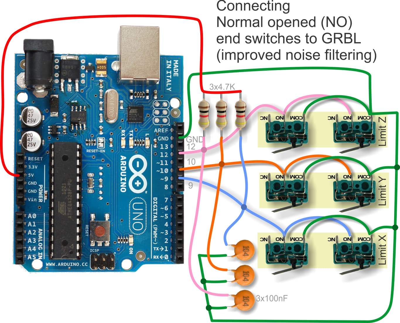
What sort of limit switches do you have? Are they configured normally closed or normally open? GRBL generally expects normally open switches.
Can you do the following:
Take close photos of the limit switches as they are wired and also how they are connected to the controller?
2.Test the limit switches at the cable on the controller side using a continuity test. Do you get continuity when limit switch triggered an no continuity when not triggered. Test on both switches.
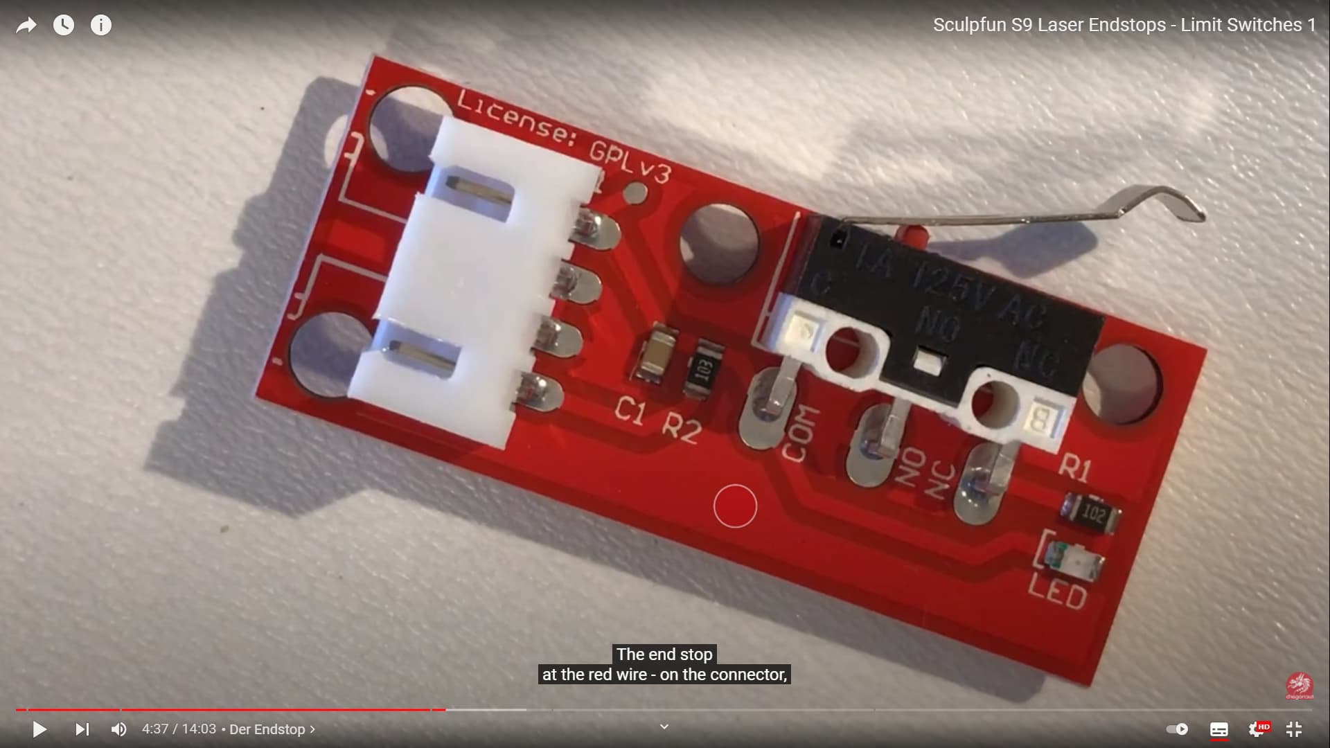
Hello. I have tested the switches. There is no current to be measured between the 2 cables when the switch lever is free. When pressed current can be measured between the poles. I do not know how to take a photo and enclose it here, so I’ll try to enclose a screen print from that lady’s (Dragoncut) video showing the switch she used. I have the same kind of switches. On her video she explains and shows that she cuts away the NC pole as only 2 poles/cables (out of 3) are needed. On her video it works perfectly. I hope the info here helps.
thanks.
and here the screenshot:
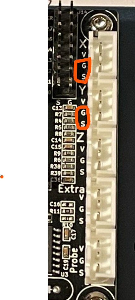
As per Mrs. Dragoncut and her videos, after cutting off the NC pin from the switch, there remains no need to carry all 3 wires originally supplied with these switches (they come with red, black and green) so I omitted the green wire and only 2 go from the switches to the plugs inserted into the sockets on the controller board. The 2 wires end up at V & G poles, in both cases. The green (discarded cable from the NC pole on the switches) would connect to the S pole.
I did another swap now: between the two wires reaching the plug on the controller. the red light light up yet the movement does not stop. The above print from console is after this last swap.