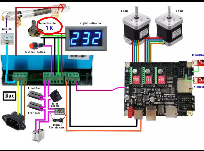
hello everyone. I would like to connect this power supply to a mks dlc32 board. I am not an expert, I have read various links but I can’t understand which is the most suitable procedure. I would like to limit the current with a potentiometer and control the power via lightburn (I would like to make engravings in gray scale). Could someone help me?
A glass tube co2 is an analog device and you set the maximum current by applying a voltage to the IN terminal of the laser. The IN terminal, pwm or dc control, will be an internally used dc control voltage.
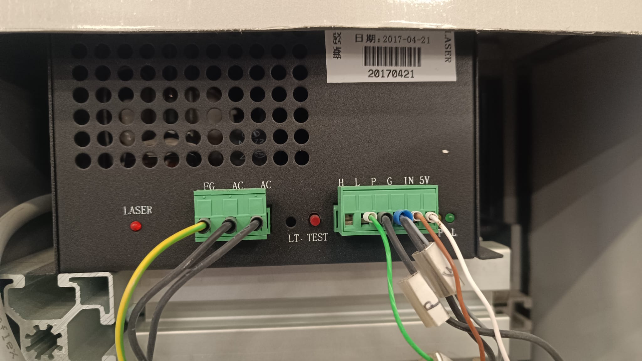
The supply you show in the wiring diagram is for a K40, which are about 30W if you’re lucky. Here it is so you relate to the pin out.
The diagram shows Spindle - of the DLC32 going to L of the lps. This is internally wired to L on the next connector. This is laser enable and is active low.
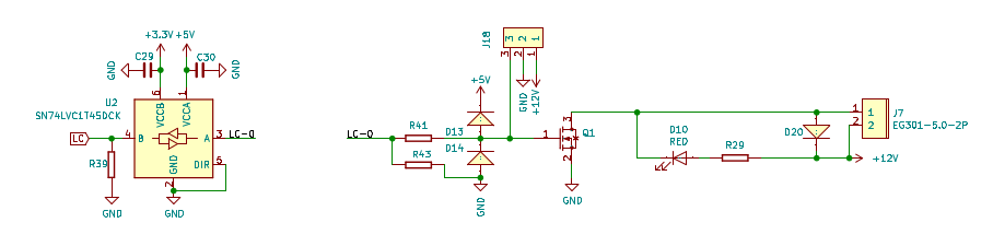
Here’s how the wiring is on the DLC32 V2.1 – J7-1 (Spindle -) goes to Q1, which grounds L, enabling it to lase at whatever current value you have set by the pot.
In effect, how this works, is you set your pot to maximum current, at least most do. The inverted pwm is used to turn the laser on/off at it’s maximum value, like a solid state laser.
On an led or rf laser you want to run at 50% power, the led or rf tube is turned on for 50% of the time and off the other 50% of the time.
My suggestion would be to use the pwm output of the led module, S, and drive the IN input with pwm. Then the current will be relative to the percentage power setting.
When I did this, I had FluidNC loaded as my firmware, I believe. I used L for a manual laser enable for the operator and P was wired to my chiller to handle a failure in the coolant flow.
Thanks for the reply. So
you advise me to exclude the potentiometer and use the Pwm directly in IN. this laser is already in operation only that I would like to replace its controller with the dlc32. Since it is used at work I would like to keep the potentiometer because otherwise some people could do damage.
I was always advised not to run my machine at 100% power. If you use the pot, then when it turns on, it’s at 100% power. So you don’t really have software control of the tubes power.
I’m not sure I follow how a pot would not work for this persons needs
the IN pin takes 0 to 5 volts. A pot allows you to set the power at some level. If 1.5 volts for example is enough for engraving then how does powering up the machine change the pot voltage?
As far as limiting current you simply use the +5 volt pin. I’m not sure how by using the PS 5 volt source you would risk over current.
Before I got a controller I used this approach to set laser power to a fixed level.
Yes this is only one output. Not ideal but this person only mentioned engraving only I believe
I monitored laser tube output. Not current on this IN pin. You could also turn the pot all the way down to zero volts then work back to a reasonable cut quality. I agree that all CO2 power supplies should monitor output current as to not stress the tube. If I recall the voltage came to between one and two volts. Nowhere near the 5 volt limit.
As far at output current limit. There are a lot of past discussions. I limit my tube to 20 mA but I rarely ever get close to that value.
The normal lps has two inputs, the IN which relates to current limiting to the tube and L which enables it to lase at the IN current limit.
If you put a manual control for the IN current limit, the software can’t control that as you’ve overridden the software pwm control to the lps.
The pwm is being used to enable the tube. It is not used to control the tubes current, which is the basis of an analog tube.
An led (or RF) laser is a digital device. It’s on or off. When you set an led to 50% power, the laser is on 100% for 1/2 the period (1/frequency) and off the other half.
A glass tube co2 can run at 50% power continuously as it’s an analog device.
Another way of saying this is, using your 20mA value, that your tube turns on at 100% anytime it turns on. If you have a mA meter, set your machine to 50%, whatever the mA meter reads is only 50% of the true current. Your meter will read 10mA although it’d allowing 20mA through for 1/2 the time.
So i recall that the PS works opposite of what you stated. H or L signals activate the tube. The voltage on IN sets the power level. If you apply a high signal on H with no voltage on IN it won’t fire. Holding H high and cycle the voltage to fire the tube is not correct. You cycle the H or L pins and hold IN at some level.
Plus you need some level on the water pin. I don’t recall which way the water is enabled. It’s a safety feature that could be wired into water, a door or estop
No need to argue the point further Jack because neither one of us are ever going to manually wire a laser PS. Anyone can google laser power supply wiring for more information.
Actually I had my dlc32 running my China Blue, so I have to disagree.
I stated exactly what you said. The L enables the laser to lase at the set current on IN. If the laser is enable, but the current limit (set on IN) is zero, it won’t lase. That’s exactly how it’s supposed to work.
However, if you want to lase at 50% the only way to do that is to set your pot for 50% … that’s not software control, it’s your hand.
It’s simply do you want to drive an analog device like it’s a digital device or as an analog device, which it is.
Thanks for your interest. For this 80w laser I should use it for both cutting and engraving. The pot could be useful to me only for a current safety system but thinking about it I could also exclude it and limit the power via Grbl but I have a doubt if I limit the power when I have to make a grayscale engraving I’m afraid I won’t get an accurate engraving. I have a k40 in the cellar that I had used some time ago then abandoned to use diode lasers and I had changed the controller with a mks sbase and I remember that I managed the current via POT and via pwm I was able to make grayscale engravings.
I had a setup using a cnc router program that turns the laser on by a stepper, cam and switch attached to the Z axis. So the program gcode drops the spindle stepper (rotates the cam into the switch) and sets the H pin high on the PS and activates the laser. I think I always used a cut depth of one millimeter to insure that the cam rotates the same amount. I might have had a toggle switch that sets high or low power by setting voltage on that IN pin. Lots of possibilities to control a laser with simple methods.