HELP! Limit switches changed & working but laser not respecting limits!

I have a co2 80w Chinese red and black with ruida controller RDC644XS
about a year ago, on start up/when homing to the top right corner, the laser head would just bang into the rails and I’d just hit esc a thousand times to get it to stop.

This happened a few times, then it was working perfectly again - until it didn’t, and has started to do this again. I was heavily pregnant at the time and had no ability to get down to change the limit switches (after asking for help on laser fb group, we suspected it was the Y switch needing to be changed)
Fast forward to today - I have changed the Y switch
On diagnoses in the ruida controller, when tapping each switch with a screwdriver, each switch lights up on the controller - i.e. they are working
Even prior to changing the switch, they were both still lighting up when tapped with metal (switches physically lighting up and also lighting up on the controller) ??working

When moving the laser using the controller, it does not respect the x axis limit or the y axis limit - still bangs into right hand rail and top hand rail.

I have read many posts and enabled, and re-written the “limit trigger” on x and y in my machine settings on Lightburn. I have tried with them both on true, both on false, resetting the controller each time - still having the problem.

?Ruida software upgrade - doesn’t seem to be a firmware upgrade for this controller.

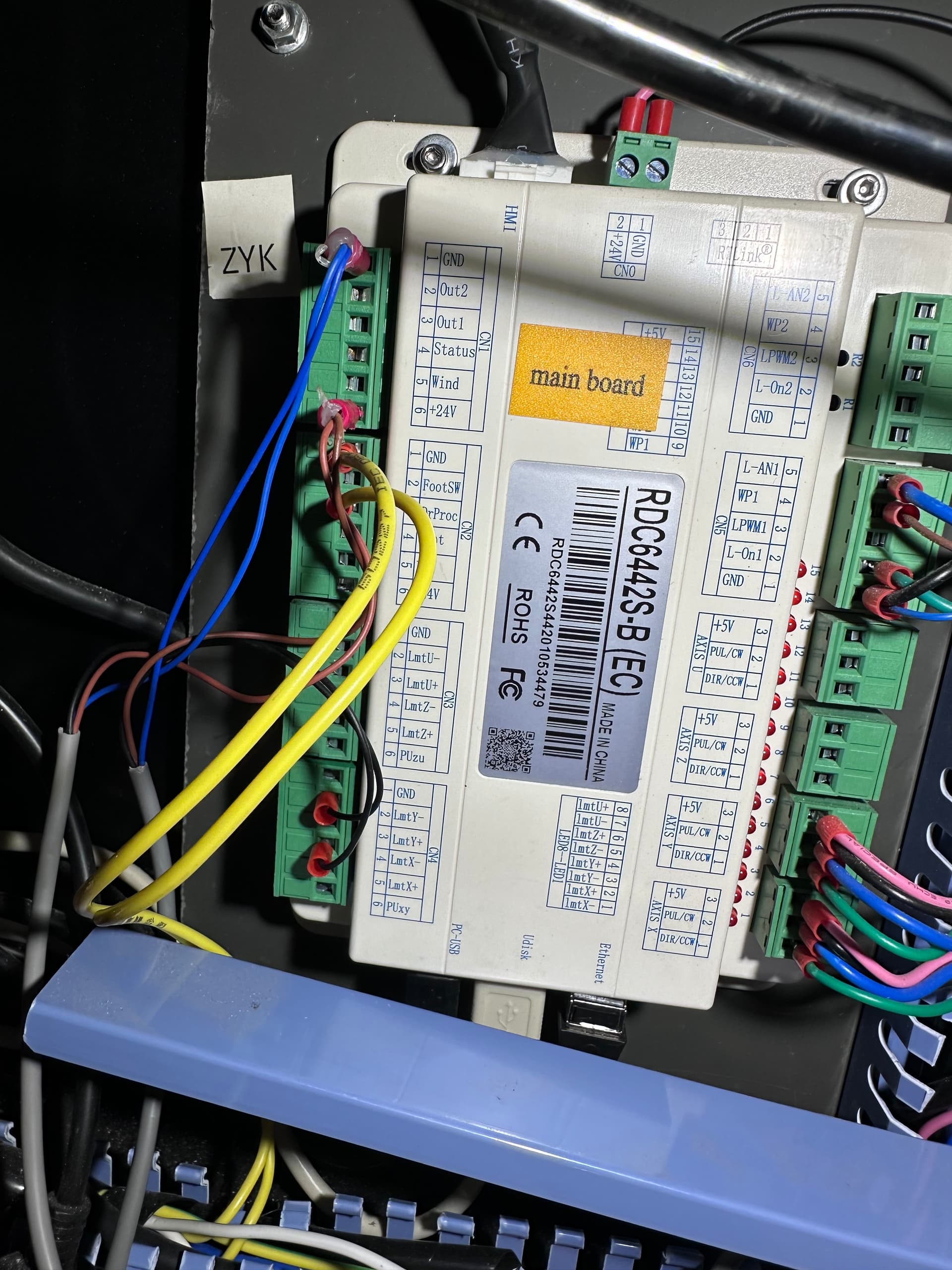
on the mainboard, (see picture), I have blue on ground, brown on +24v, and black on lmtY- & lmtX-

completely stumped, anyone have any other ideas???

If the switches work by placing something metal over them it could be that the plate that is supposed to trigger the switch is too far above the switch to consistently trigger it. See how much space there is between the switch and the plate. If you have a small bar magnet that you can place on the bottom of the plate for testing that would verify if that is the issue and then work towards permanent repair.

Try a slow feed (G0 X300 Y300 F50 S10) and do the screwdriver thing to see if it stops. If not, you most likely have a classic wiring issue with the switches. I do not know your system, but somebody with one can provide additional diagnostic steps.

This is not I would expect on any system. I would have guessed Blue is the switch output signal if I did not have a diagram. Do you have a wiring diagram for the switch? If so, posting it here would be a great help.

Heh. You think colors mean anything? Hah! :rofl:

That is, for whatever it’s worth, apparently the standard color code for those proximity switches, as I found out after being forced to stick my head inside the laser:

As the bluesman said, if it weren’t for bad assumptions, I wouldn’t have no assumptions at all …

2 Likes

Can you explain/simplify this? Sorry!

Can you enter commands in the Console window? If so, that string should jog the laser very slowly, giving you tile to do some testing with the proximity switches. I do not know how robust the Ruida controller is, so bad I/O inputs might be the culprit.

I am a GRBL guy, so I was responding as an electronics technician (60+ years experience).with mostly USA equipment. I know the Chinese wire code depends on what is in the factory this week. As @ednisley pointed out, I made a loose assumption.

Remember: Ruida controllers don’t use GRBL and have a binary interface, so there’s no G-Code and no Console.

So the initial diagnosis seems correct: something is wrong with the home switch or switches.

Ruida controllers have a nightmare failure mode:

  • The switch works
  • The diagnostic display for that input lights up
  • Homing is enabled
  • The configuration is correct
  • But the controller ignores the switch input
  • And there’s nothing you can do about it

Before jumping to that conclusion, however, let’s (re)verify the gantry activates the switches.

Don’t change anything in the configuration; homing should be enabled.

With the machine power off, unplug the motor wires from both the X and Y axis stepper drivers. Those are the green blocks with four wires plugged into the Motor connector, labeled A+ / A- / B+ / B-. If there’s enough hot melt glue slobbered over the adjacent power connector (with two pins: GND / VCC) to bond them together, you can pull that one, too.

When you turn on the machine, it will try to home, but the motor are dead and it won’t thrash around. Hit Esc on the panel to cancel the homing operation; the display should show both axes at 10,000 mm.

With the motors dead, you can easily push the laser head and gantry by hand.

Get to the controller’s diagnostic display, then:

  • Verify the LmtX- indicator is off
  • Shove the laser head to the right until the X axis switch lights up
  • Verify the LmtX- indicator is now on

Do the same thing with the LmtY- indicator and the gantry.

Note: The switches must be wired to the LmtX- and LmtY- inputs, not the LmtX+ and LmtY+ inputs.

If either + indicator lights up, that switch is wired to the wrong input terminal. Move the (black) wire from the + terminal to the adjacent - input terminal and check again.

Take pictures of the diagnostic display with the laser head shoved into the right rear corner and those two diagnostic inputs lit up, so we can look over your shoulder.

With the machine power off, plug the stepper motor connectors into the drivers to restore what passes for normal operation.

Report what you find …

1 Like

It looks like it’s wired correctly and it is responding to the active sensor by the led on the controller illuminating.


Might also check the Ruida console Z/U → Diagnoses and see that it’s making it inside the controller.

My water protect input showed it was working at the Ruida external led, but never showed active via the consoles diagnosis display. This is my 6442g controller and it should look something like this. Shows XLimit- active and Water prot1 active.


Disable one of the axes from homing, in either order. If they both fail, we’ll have to look elsewhere. If one of them works, then we can zero in on the non working axes.

I use an open collector hall effect with your wiring. It sounds like you have it wired correctly, but just wondering Is your switch like this?

Brown is supply, blue is ground and black is the output… on this one :face_with_spiral_eyes:

Before you modify anything within the Rudia controller, ensure you save an original copy for future reference.

I keep the original on my machine, one on a backup and one on my google drive…


Nice pictures, not only legible – right side up too. :tada:

I can follow your wiring, looks good.

Good luck

:smile_cat:

This I remember. What I fail to remember is the not everyone lives in a GRBL world. I Try to check the machine type for what the controller might be,. Sometimes the complaint is so generic that I fail to do that. My apologies to @epop for not paying better attention. I am not worried about being senile, but doing stupid things is starting to concern me! :joy:

We appreciate the help anyway, so don’t let it keep you up a night.


You do know you can click on the users name and hopefully have a list of their machines?

:smile_cat:

1 Like

I think in GRBL. I have no other machines so forget that there are not only non GRBL but also modified versions of GRBL.
Maybe I’ll make this my disclaimer for bad advice.

1 Like

I have some t-shirts on that subject … :face_with_head_bandage:

1 Like

Yeah, when I remember!

1 Like