I recently purchased a UV printer and I’m trying to set up a reliable print-and-cut workflow with my laser, but I’m completely stuck.
My laser is a red and black 60W 500x700 Chinese CO2 laser from eBay running LightBurn. I’ve been fighting this issue for over a month now and I’m wasting a lot of time, material, and money trying to get these leatherette patches cut correctly.
Here’s what’s happening:
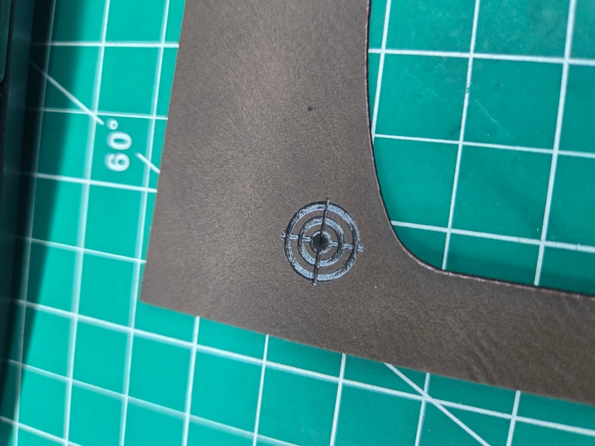
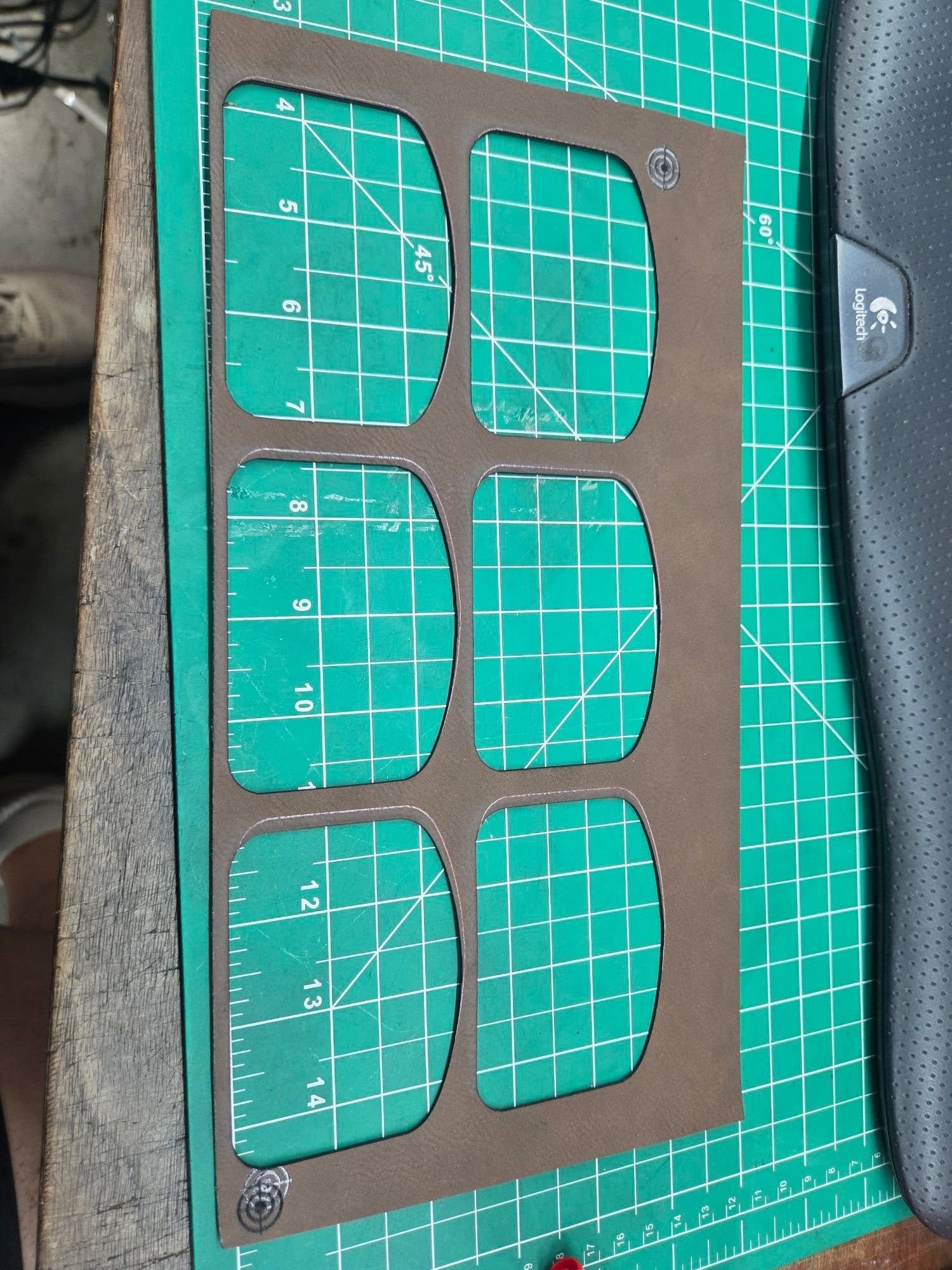
I am laying my leatherette sheet in the upper left hand side of the bed. When I set up my registration targets in the upper left area of the sheet, I can get the target almost perfect by using 1mm jog movements and the pulse button. But when I jog over to the next target, I notice the laser always lands to the right of where the printed target actually is on the leatherette. I continue adjusting it 1mm at a time and pulsing until it visually lines up.
The strange part is when I actually start the job. It looks like the laser should be cutting inside the printed outlines, but the cuts end up nowhere close to where they should be.
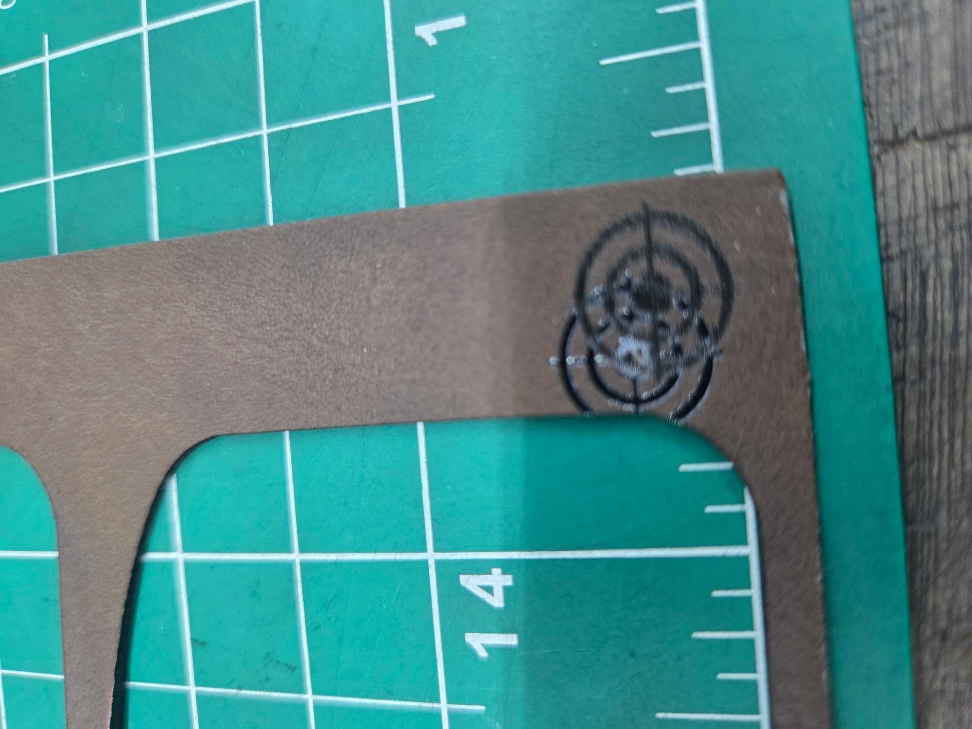
To troubleshoot, I changed my workflow and had the targets engrave after the cut so I could compare the alignment. The top left target engraved perfectly, but the bottom right target engraved about 5mm to the right and slightly lower than the original printed target.
I have already calibrated the X and Y axes in LightBurn multiple times using a 4x4 inch square test cut. Even after entering the corrected calibration values, absolutely nothing changes.
At this point I’m trying to figure out:
What would cause alignment to be accurate in one area of the bed but off in another?
Does this sound like a gantry squaring issue, belt issue, backlash, or something else mechanical?
Why would calibration appear to change nothing?
Is there a better workflow for print-and-cut on small leatherette patches?
Any advice would be greatly appreciated because I’m at the point where I can’t trust the machine to cut consistently at all.
I confess that I’ve never had much success with the print and cut function, but I always ended up doing it another way, and trying to understand what I did wrong afterwards, but it never happened.
There are some videos on YouTube that give some tips on misalignments, scales, etc.
The very little I can help with is:
No, that would be revealed in the alignments of the 4 x 4 inch square that you already performed.
Because everything is calibrated and the problem is not related to calibration.
Perhaps, always using “Absolute Coords,” create a template system where you place the pre-cut pieces and center the engraving as needed.
A template that could be fixed in some way, always guaranteeing the same position, with the cuts filling as much of the workspace as possible, and arranging the engravings (in Lightburn) as needed.
I have some difficulty explaining exactly what I mean, but there are plenty of examples of this here.
I’ll leave this video as an example.
I believe it will work even better than the print and cut function.
In my opinion, this function is more intended to complete a job that has to be divided into several sections because the dimensions are larger than the workspace.
Are you using a camera to visually line up the target? From what I’ve read here, I don’t believe so, but I’d like to remove the possibility of another variable.
Out of curiosity… What are the straight-line distances between the registration marks in LightBurn and on the leatherette before beginning?
The first thing that came to mind was the material moving or shrinking while laser cutting, but the anticipated position of the second target before cutting isn’t where it’s expected to be.
Thanks for replying, I don’t use a camera. I will need to measure the distance of the targets this evening on the material and see if they match what is on Lightburn. I guess it is possible that the leatherette is shrinking, UV does use heat while printing. I make sure the material doesn’t move with the usage of magnets.
Thanks, at this point I am willing to try anything. The UV printer is useless to me at this point as far as hat patches go until I get this figured out, and hat patches were the main reason I purchased it.
I set the Ruida controller’s manual step size to 0.2 mm, use its Fast/Slow button to scoot close to the printed target, then make teeny steps to align the dot at the center; it seems easier to do all that on the machIne’s display than long-reaching to the PC’s keyboard.
You must also verify:
The red-dot pointer is coincident with the CO₂ laser beam at the focus distance
The laser is focused on the surface of the material
The material is flat so everything is at the focus distance
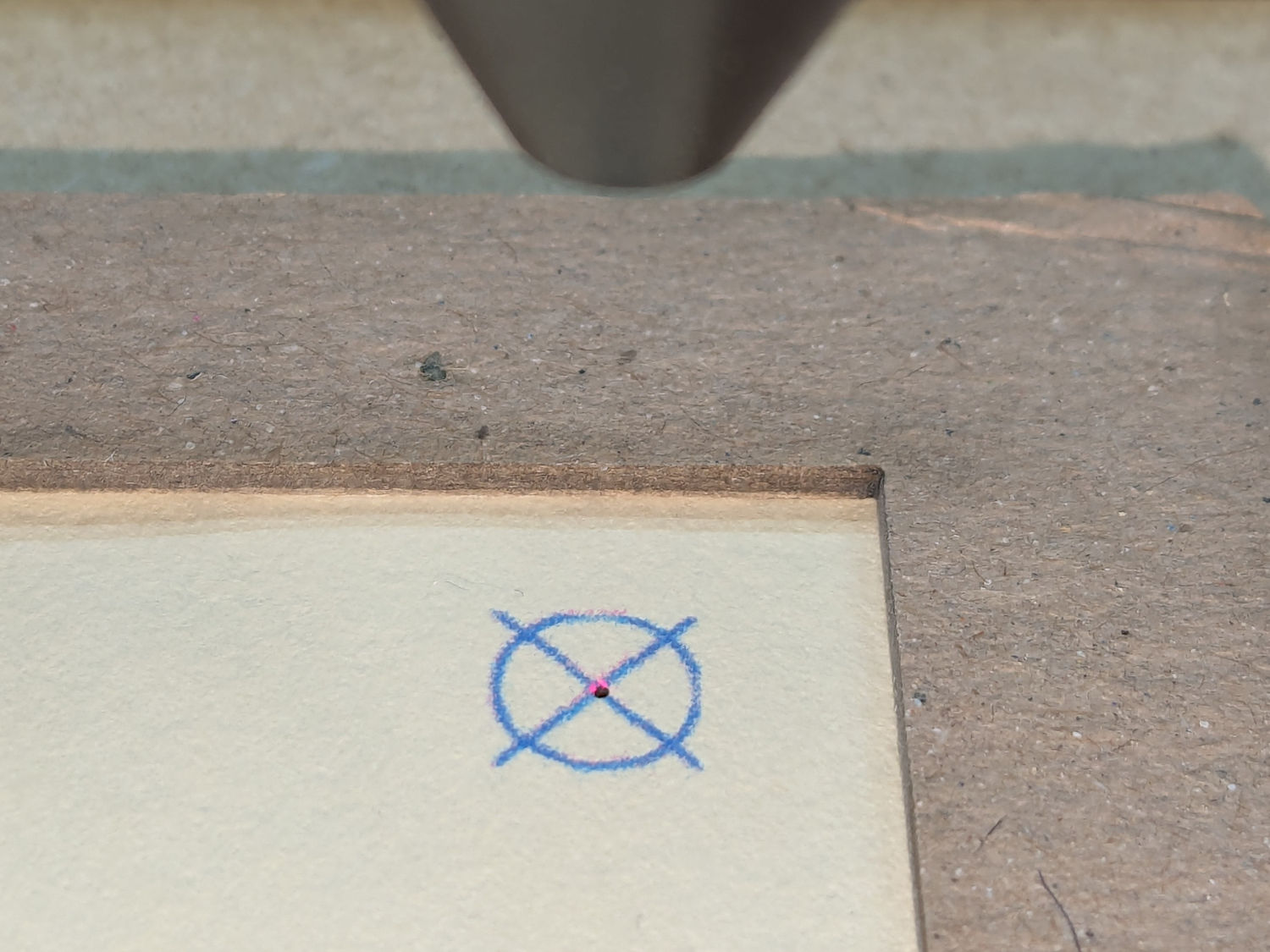
For critical items, I fire a test pulse after aligning the red dot to the printed target:
You may get better accuracy with a less-chunky target. I use a vector cross, rather than engraved bars:
That pattern produces the target printed on the paper, although the inkjet-printed lines are much thicker than the vector pattern in LightBurn.
All of which seemsis incredibly tedious, but most of it is once-and-done setup. I’ve found I must be grindingly meticulous about everything, because Print-and-Cut has absolutely no sense of humor and will convert “pretty close” accuracy into totally wrong results.
Are you using the “with scaling” option in LightBurn or no?
If you aren’t, the 1st point is the “anchor” and the 2nd one controls rotation only. If the job in LightBurn doesn’t perfectly match the job on paper (or your machine’s axis calibration is off) the physical results won’t match either.
A couple things to check:
Measure the distance between the centers of the targets with a mm-scale ruler or calipers.
Run the job from LB on some cardboard and measure the same distance
Do they match?
Does the measured distance between the shapes in LightBurn (using the ruler tool) match the distance between them on the output?
If any of those are off, you’re starting with trouble already.
Yeah, that’s part of the problem then. If you have any scaling difference between the two devices you’ll want to use the “with scaling” option.
It’s important to understand that you might not be intentionally scaling them differently, but the devices themselves might not be calibrated identically, which is what the “with scaling” option is intended to fix.
Fun fact 1: inkjet printers have different “calibrations” along the X and Y axes.
Fun fact 2: The Y axis “calibration” depends on how good a grip the feed rollers got on the paper.
Fun fact 3: The paper can roll through the printer at a slight angle, misaligning the pattern with the axes.
My decent-quality Canon inkjet prints images just slightly too large along both axes. Scaling X by 97.0% and Y by 97.9% made the printed pattern line up with the engraved holes:
Across the width of the card, not correcting that 3% error produced a brutally obvious 5 mm offset.
For cardboard, I’ve been using cereal boxes. They’re thicker that card stock and might be considered as a free byproduct of your favorite breakfast cereal. Small boxes are great, Family sizes are better.
I keep a flat stack with the tabs cut off nearby.
Just to be clear, don’t use the corrugated cardboard as the voids make for difficult cutting (if not impossible).
That would be a problem - We don’t correct for different scale in X & Y during Print and Cut. There are plans to make a 3-point and 4-point version, which will correct for scale & skew, and even warp (respectively), but doing those point registrations manually will be a bit painful.
TBH, Print-and-Cut was entirely too heavyweight for what I needed.
After I sorted out the scale factors, I set up two saved positions where the targets should be, then skootched the fixture to match. Iterate once to check and it’s all lined up.
While it can be a bit tedious, I’m a huge fan of “print & cut”. I however, have never used it for printing and cutting. I use it to print larger than my cut area. I’ve printed things up to 40 inches (so three separate burns) with great success - which would have been close to impossible without print and cut.
Do you have any ETA on this feature? We have just upgraded to the Thunderlaser Titan 35 with head-mounted camera and in desperate need of professional software to use with it. The Lasermaker software Thunderlaser use is a bit underwhelming. We are a business with quite good technical understanding of laser mechanics and software so would be happy to help out with any testing you require on this machine in regards to print and cut with rego marks.